Pico GFX-70 Controllers Bulletin 1760 Series Quick Start
Important User Information Solid state equipment has operational characteristics differing from those of electromechanical equipment. Safety Guidelines for the Application, Installation and Maintenance of Solid State Controls (Publication SGI-1.1 available from your local Rockwell Automation sales office or online at http://www.ab.com/manuals/gi) describes some important differences between solid state equipment and hard-wired electromechanical devices.
Table of Contents Chapter 1 Overview of Course 1 Course 1 Objective. . . . . . . . . . . . . . . . . . . . . . . . . . . . . . . . . . . . . . . . 1-1 Task Definition for Course 1. . . . . . . . . . . . . . . . . . . . . . . . . . . . . . . . 1-3 Chapter 2 Lesson 1 Creating a Pico Project. . . . . . . . . . . . . . . . . . . . . . . . . . . . . . . . . . . . . Creating a Circuit Diagram . . . . . . . . . . . . . . . . . . . . . . . . . . . . . . . . . Circuit Diagram Simulation . . . . . . . . . . . . .
Table of Contents 2 Publication 1760-QS002A-EN-P - April 2004
Chapter 1 Overview of Course 1 Course 1 Objective Course 1 is designed to help you get to know the PicoSoft Pro user interface. The procedures will acquaint you with the three sections of the user interface and the four different views that you will use. Take advantage of this course to see how simple it can be to work with PicoSoft Pro.
1-2 Overview of Course 1 After completing Course 1, you should be able to: • • • • • Create a project, Wire up a circuit diagram, Test a circuit diagram, Transfer it and Print it out. TIP TIP To make optimum use of PicoSoft Pro, you must ensure that your screen is using a resolution of 1024 x 768 pixels and small fonts (96 dpi). The necessary settings can be made via Start, Settings, Control Panel, Display, Settings.
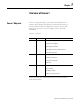
Overview of Course 1 Task Definition for Course 1 1-3 The example procedures will refer to the following system. A conveyor belt system that is driven by a three-phase motor is to start up with a delay of 3 seconds after it has been switched on. The conveyor belt is used for transporting packages. Once a certain number of packages have been transported, the system should switch off after a specified rundown time.
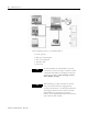
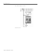
1-4 Overview of Course 1 The connection diagram is as follows: Proceed to Lesson 1.
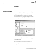
Chapter 2 Lesson 1 Creating a Pico Project To create a circuit diagram in PicoSoft Pro for a Pico controller, you first have to create a project. The project consists of the device (e.g. 1760-IB12XOB8) and the associated circuit diagram. You can start a new project by left-clicking File then New. The PicoSoft Pro user interface is divided into three sections. The following figure shows you the user interface in the Project View.
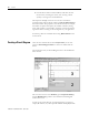
2-2 Lesson 1 2. Click the device called “1760-L12AWA”, hold down the left mouse button, and drag the mouse (now showing a device symbol) to the right onto the Workbench. The Properties field [2] now shows an overview of the device properties. Right-click the device and choose Device Information in the context menu. The properties of the device include, for example, the number of inputs and outputs, the number of markers, timing relays, and counters.
Lesson 1 2-3 Toolbox [1] and can be logically linked together in the Circuit Diagram window [3]. You can specify the properties of the operands in the Properties field [2]. To develop a solution for our task, we first have to wire up the inputs I1 and I2 in our circuit diagram so that they act on marker M1, which in turn is responsible for the on/off switching of the motor. To use input I1 in our circuit diagram, proceed as follows: 1.
2-4 Lesson 1 Circuit Diagram Simulation You will need to select Simulation View to test the wired circuit diagram. Activate the Simulation View via View, Simulation or by clicking the Simulation button at the bottom of the Toolbox. The following figure shows the Simulation View in PicoSoft Pro. The Simulation View is also divided into the three areas of the PicoSoft Pro user interface. The Toolbox [1] contains the simulators for the inputs and different dialogs for setting simulation parameters.
Lesson 1 2-5 4. For example, to view the status of a marker in the Properties field window, simply double-click the marker you wish to monitor. 5. Click the Stop button Establishing a Connection with the Device to stop the simulation. Now that we have tested the circuit diagram, let's download it to the device. To do this, connect your device to the PC using the 1760-CBL-PM02 cable available as an accessory. Choose Communication, Interface, select the interface required (COM 1 ...
2-6 Lesson 1 Don't worry if the circuit diagram suddenly appears empty. This area is used to display the current state of the circuit diagram when it is running in the device. More about this later. First, we need to transfer the circuit diagram to the device, and then start the device. The Toolbox [1] will help us to do this. Proceed as follows: 1. Click the Program button in the Toolbox. This will open the dialog for downloading and uploading the circuit diagram. 2. Click the Download button.
Lesson 1 3. Click the Stop button 2-7 to stop the Power flow display. You have now been shown the four views of PicoSoft Pro and are now able to: • • • • Select a device for the project (in Project View) Create the circuit diagram (in Circuit Diagram View) Test the circuit diagram (in Simulation View) Transfer the circuit diagram to the device (in Communication View) We will now learn how to document the project.
2-8 Lesson 1 Publication 1760-QS002A-EN-P - April 2004
Chapter 3 Lesson 2 Wiring a Pico Controller Timing Relay Back to our task. In order to extend the circuit diagram for our conveyor belt system we have to switch to Circuit Diagram View. As we know from Lesson 1, there are several ways to change views. We can either use the menu (Circuit Diagram, Circuit Diagram View) or the tab in the Toolbox. However, there is a more convenient and faster way of reaching this view. Double-clicking the device is enough to activate the Circuit Diagram View.
3-2 Lesson 2 The T1 contact activates coil Q1 once the delay time has elapsed. The parameters for T1 are assigned when the function relay is entered: TIP Timing Relay Simulation PicoSoft Pro does not have an “Autosave function”, so it is advisable to save the circuit diagram you are creating at regular intervals (File, Save). To check the extended circuit diagram, choose View, Simulation to move to the Simulation user interface. In this lesson we will observe the switching behavior of timing relay T1.
Lesson 2 3-3 1. Clicking the Display button in the Toolbox, 2. Double-clicking the text T Timing Relays, 3. And then clicking T 1-2 to switch to the Properties field. Now, start the simulation by clicking the Start Simulation button . You can now actuate switches I1 and I2 in the Simulator for the I inputs so that the timing relay T1 is started. The output Q1 will then be switched on after the on-delay of 3 seconds has elapsed. Close the simulation via Simulation, Stop.
3-4 Lesson 2 TIP Using Notes The connection to the device will be cleared as soon as the Communication View is closed. PicoSoft Pro will therefore deactivate the menu items in the Communication menu. The only exception to this is the COM interface selection. PicoSoft Pro enables you to attach notes to individual rungs to add comments to your circuit diagram. To use these freely definable comments, switch to Circuit Diagram View (for example, via View, Circuit Diagram).
Lesson 2 3-5 • To delete the note, position the cursor on the note field, right-click the mouse, and choose Delete Note. • If the notes are visible, they will be printed out with the circuit diagram (File, Print...). The toolbar features the Note button and four other tools for editing your circuit diagram: • Cross-reference list, for displaying this list in the Properties field window . • Select Area for selecting areas of the circuit diagram for deleting or copying .
3-6 Lesson 2 Publication 1760-QS002A-EN-P - April 2004
Chapter 4 Lesson 3 Adding Rungs and Drawing Connections Now let us focus entirely on our solution. Light barrier S3 supplies count pulses via I3 for the packages that are transported on the conveyor belt. These are connected to the C input of Counter 1 for as long as the motor is running. The Reset condition for Counter 1 is present when the motor stops (Q1 = 0).
4-2 Lesson 3 Up to now, only I2 was used to stop the motor manually. Both manual and automatic stop conditions can be implemented by wiring the counter output as a make contact parallel to I2. To do this we add an empty rung between rung 2 and 3. This is done by positioning the cursor on rung 3 and adding a new rung via Edit, Insert Rung. The counter contact 1 is then linked as follows: To draw a vertical connection line between rung 2 and rung 3, you need the Pen from the Toolbox.
Lesson 3 4-3 A rundown time of 4s after the switch off time is required to allow all packages to completely come off the conveyor belt. This delay is provided by T2 which activates the switch off as an on-delayed timing relay. For this we shall modify the circuit diagram as follows: The output of C1 triggers T2 which then controls M1 in rung 3 instead of C1.
4-4 Lesson 3 Changes in the I/R Function dialog change the switching characteristics of the I or R input simulators. 1: “Momentary make contact” function 2: “Momentary break contact” function I input simulator for the device. Once the settings described above have been made, you can then start the simulation by clicking the Play button in the Toolbar. Watch the effects of the modified functions of the I input simulator.
Lesson 3 Uploading a Program 4-5 We will now “upload” a circuit diagram from the device. PicoSoft should be able to create the project automatically for us. 1. Save your project via File, Save As.... This will open a standard Windows file save dialog. Give the project a suitable name (e.g. “conveyorbelt”) and save it via the Save button. The project will be saved with the file suffix e40. 2. Now close the project via File, Close (not Exit). 3.
4-6 Lesson 3 6. Re-establish an online connection to the device (menu: Communication, Online). 7. Once the connection has been established successfully, you can then transfer the circuit diagram into PicoSoft via Communication, Program, Upload. 8. If the circuit diagram upload was successful, you can view it in the Circuit Diagram View (View, Circuit Diagram) and see the associated device in the Project View (View, Project).
Lesson 3 4-7 4. Left-click a comment field (in our example the comment “Emergency-stop” was assigned to I2). 5. Type your comment and press Enter. This will assign the comment to the operand directly in the circuit diagram. 6. The cross-reference list can be printed out via File, Print... and thus added to the project documentation. When you are comfortable with the information presented in Course 1, proceed to Course 2.
4-8 Lesson 3 Publication 1760-QS002A-EN-P - April 2004
Chapter 5 Overview of Course 2 Course 2 Objective Course 2 assumes the learner already has a general knowledge of using PicoSoft Pro. If this is not the case, please go through Course 1 first. The exercises in Course 2 primarily describe how to create a project for Pico GFX-70 devices. However, users of other Pico controllers can also take part in this course to get acquainted with the wide range of functions available with the Pico GFX-70 devices. The course consists of two additional lessons.
5-2 Overview of Course 2 Publication 1760-QS002A-EN-P - April 2004
Chapter 6 Lesson 4 Creating a Pico GFX-70 Project We learned how to create a project in Lesson 1 (reference: Creating a Pico Project on page 2-1). We are now going to create our first project which has remote expansion I/O as well as the Pico GFX-70 basic unit. To create a project: 1. We shall start a new project via File, New. 2. We then open the device tree for the 1760-DU series in the Toolbox by double-clicking the Device icon, or clicking the “+” sign. 3.
6-2 Lesson 4 You can then make all the necessary settings in the appropriate tabs. The settings will be downloaded to the device together with the circuit diagram. 4. The Mode tab should be the first tab to be activated. The Mode area indicates at Display that this first basic unit is initially configured for stand-alone operation. 5. Select the System tab.
Lesson 4 Program, Circuit Diagram, and Function Block Diagram 6-3 Let us switch to Circuit Diagram View and look at the operands provided in the Toolbox. As you can see, there are a number of new operands available for programming Pico GFX-70 devices. As with Pico projects, the circuit diagram contains contacts and coils that are linked together via connection lines. These contacts and coils can, for example, be the inputs and outputs of the controller.
6-4 Lesson 4 1. Drag the P Button operands and counter (C..) in succession from the Toolbox, drop them onto the circuit diagram and arrange them as shown in the following figure. 2. The Properties field window in the Mode tab will propose the operand number 1. We will accept the proposed number 1. The first line of our program will look as follows: 3. As the counter function block is to count the rising edges only, we must select the option C_ counter coil and Rising edge in the list box. 4.
Lesson 4 6-5 This enables the parameter set of the function block to be called and modified on the device during operation. For this, the program must have been transferred to the device beforehand. We have now wired the most important function block in our mini project and defined its parameters. However, the counter function block is then not only displayed in the circuit diagram. Unlike Pico projects, Pico GFX-70 projects also have a function block diagram as well as the circuit diagram.
6-6 Lesson 4 setpoint SH). We can use this signal in the circuit diagram to reset marker byte 1 to zero. The function block coils are located on the left of the function block and are also shown in normal type. These coils are needed for activating a function block or supplying it with count pulses. We have already implemented the supply of the count pulses via C_. If you have used any contacts or coils in the circuit diagram, this is highlighted in the function block with green circles .
Lesson 4 6-7 What is now still missing is the resetting of the counter when the actual value has reached 16. We also want to zero the wired outputs. To do this, we use the function block contact OF of the counter. As previously described, OF is set to “1” if the counter actual value is greater than or equal to the upper setpoint. OF then switches the reset input of the counter as well as activating the MR - Master Reset function block, which, in turn, clears marker byte 1.
6-8 Lesson 4 2. To view the status of the outputs, click the Display button in the Toolbox and click the Q Outputs tree structure. The Properties field window shows the outputs as round grey symbols. 3. To view the states of the function blocks as well as the outputs, we have to switch to function block diagram via menu: View, Function Blocks or directly via the button. The simulation can also be started by clicking the toolbar. button in the 4.
Lesson 4 6-9 2. Select Program 1 and Function Blocks 1. 3. Click the OK button to send the print job to the printer. Proceed to Lesson 5.
6-10 Lesson 4 Publication 1760-QS002A-EN-P - April 2004
Chapter 7 Lesson 5 Pico GFX-70 Pico-Link Project When using Pico GFX-70 devices, you can connect several basic units. This connection is implemented using Pico's Pico-Link. This CAN-based intraconnect allows up to 8 devices to communicate between each other. The entire Pico-Link intraconnect can be up to 1000 meters in length. A Pico-Link intraconnect consists of at least two basic units, with the first one being the master and the second one being the slave.
7-2 Lesson 5 Since PicoSoft Pro sets everything automatically for you, that's all you have to do. But what did PicoSoft Pro do for us? Let's start once more from the beginning to examine the steps in more detail. 1. Close the current project via File, Close without saving it. 2. Open a new project via File, New. 3. As described above, we then add a 1760-LDFC CPU module, a 1760-DUB display module and a 1760-IB12XOB4IOF I/O module to the Workbench using drag and drop.
Lesson 5 7-3 5. You will be asked to enter a Pico-Link ID (station number). PicoSoft Pro will propose the Pico-Link ID = 2. After entry, you will be asked to enter the device version number and confirm the Pico-Link ID = 2 via the OK button. PicoSoft Pro will now create a Pico-Link intraconnect. The first device is automatically assigned Pico-Link ID 1 and is “promoted” to master. The second device is assigned Pico-Link ID 2 and thus automatically becomes a slave.
7-4 Lesson 5 TIP PicoSoft Pro primarily uses the term Pico-Link ID for station number. In other words: Pico-Link ID = Station number. 2) With the SLAVE (Pico-Link ID 2) Pico-Link Configurator Pico-Link ID The Pico-Link Configurator area for the slave looks quite different. Here you can select or deselect both Send IO and Remote RUN. The selection for Remote IO always remains inactive and is automatically determined by PicoSoft Pro.
Lesson 5 Description Send IO If the inputs/outputs of another device are to be made accessible to the other Pico-Link stations, Send IO must be activated. 7-5 Master Slave (Pico-Link ID=1) (Pico-Link ID=2...8) Can be set Can be set Cannot be set, is always disabled. Can be set Cannot be set, always = 1 Can be set between 2...8 In this case, the states of the inputs and outputs are made available cyclically to the Pico-Link intraconnect and thus to the other Pico-Link stations.
7-6 Lesson 5 We shall not, however, discuss the possible settings of Baud Rate and Bus Delay any further at this point. For the purposes of our exercise, we will use the default values offered. To complete our project, only the third device is now required. 1. We then add a 1760-LDFC processor module, a 1760-DUB display module, and a 1760-IB12XOB4IOF I/O module to the Workbench using drag and drop. 2. A Pico-Link ID address is automatically proposed in the same way as when the second device was added.
Lesson 5 7-7 Program for Device 2 (Pico-Link ID 2) The Properties fields for the two bit outputs must be set as follows: Bit output SN 1 Bit output SN 2 Enter the number of the operand in the SN list box, 1 for SN1 and 2 for SN2. The preceding station number (Pico-Link ID) must be set to 1 for both SN operands since the signals are to be sent to the Pico-Link station 1 (master). To read the P buttons, we must enable them beforehand. 1. To do this we return to Project View and left-click Device 2.
7-8 Lesson 5 Activating P Buttons We have previously implemented the reading of the P buttons on device 2. We must now further process the information obtained, i.e. the pressing of the P1 button is incremented and the counter state is reset to zero using P2. We wish to assign the logical processing of the data in our example to the master. As we are now in the Project View we can double-click Device 1 (Pico-Link ID 1) to activate circuit diagram entry for the master.
Lesson 5 Bit input RN 1 7-9 Bit input RN 2 The following table shows the relationship between the SN and RN operands: Send bit via 1SN1 from Pico-Link ID 2 Read sent bit via 2RN1 to Pico-Link ID 1 1: Bit is meant for station 1 (Pico-Link ID 1) 2: Bit comes from station 2 (Pico-Link ID 2) SN: The bit is sent RN: The bit is read 1: Operand number (is between 1-32) 1: Operand number (is between 1-32). Must be identical to the number of the SN operand.
7-10 Lesson 5 Complete circuit diagram of the master. To address the output of the input/output module (Pico-Link ID 3), rather than the local output Q1 of the master, we have to assign the output Q1 with Pico-Link ID 3. Properties of output 3Q1. That's it! The programs have been written and just have to be downloaded to the devices.
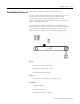
Lesson 5 7-11 We must also connect the PC to the master that is always represented by the device shown on the far left (see following figure). For this we require the 1760-CBL-PC02 PC connection cable. Three stations connected via Pico-Link. The figure above shows the Pico-Link configuration consisting of three stations (1), two Pico-Link connection cables 1760-CBL-INT01 (2) and two bus terminating resistors 1760-TERM1 (3).
7-12 Lesson 5 TIP Fortunately, PicoSoft Pro does this all for us providing the following conditions are met: The 1760-CBL-PC02 PC connection cable is plugged in on the master and the connection from the PC to this device is Online. We now simply have to start the configuration via Communication, Configuration, Pico-Link. PicoSoft Pro starts to transfer the Pico-Link intraconnect configuration to the master immediately.
Lesson 5 7-13 To start program execution, open the Program dialog in the Toolbox and click the RUN button. As Remote RUN was set on all devices, this command is applied to all three devices, i.e. all devices in the Pico-Link are switched from STOP to RUN. As mentioned in previous lessons, we can display the states in the devices in PicoSoft Pro via Communication, Status Display On. As we have selected Device 1 via Communication, Device, Pico-Link Operation, we can view the online power flow in the master.
7-14 Lesson 5 1. Move from the circuit diagram to the function block diagram via View, Function Blocks or directly via the button. 2. Return to the Circuit Diagram View by clicking the more. button once You may wonder how you can display the states of the second device in PicoSoft Pro. Do I have to disconnect the PC from the device and reconnect the 1760-CBL-PC02 somewhere else? No, it is much easier to do. 1. Choose Communication, Device, Pico-Link Operation to select Device 2.
Rockwell Automation Support Rockwell Automation provides technical information on the web to assist you in using our products. At http://support.rockwellautomation.com, you can find technical manuals, a knowledge base of FAQs, technical and application notes, sample code and links to software service packs, and a MySupport feature that you can customize to make the best use of these tools.