Pico DeviceNet Communication Interface 1760-DNET User Manual
Important User Information Solid state equipment has operational characteristics differing from those of electromechanical equipment. Safety Guidelines for the Application, Installation and Maintenance of Solid State Controls (publication SGI-1.1 available from your local Rockwell Automation sales office or online at http://www.rockwellautomation.com/literature) describes some important differences between solid state equipment and hard-wired electromechanical devices.
Table of Contents Preface Who Should Use this Manual. . . . . . . . . . . Purpose of this Manual . . . . . . . . . . . . . . . Common Techniques Used in this Manual . Rockwell Automation Support . . . . . . . . . . . . . . . . . . . . . . . . . . . . . . . . . . . . . . . . . . . . . . . . . . . . . . . . . . P-1 P-1 P-2 P-3 System Overview . . . . . . . . . . . . . . . . . . . . . . Structure of the Unit . . . . . . . . . . . . . . . . . . . . Communication Profile . . . . . . . . . . . . .
Table of Contents 2 Read/write function block data . . . . . . . . . . . . . . . . . . . . . 7-20 Analysis – error codes via PicoLink . . . . . . . . . . . . . . . . . . 7-64 Chapter 8 Troubleshoot Your Controller Chapter A Specifications Technical Data . . . . . . . . . . . . . . . . . . . . . . . . . . . . . . . . . A-1 Dimensions. . . . . . . . . . . . . . . . . . . . . . . . . . . . . . . . . . . .
Preface Read this preface to familiarize yourself with the rest of the manual. It provides information concerning: • • • • • Who Should Use this Manual who should use this manual the purpose of this manual related documentation conventions used in this manual Rockwell Automation support Use this manual if you are responsible for designing, installing, programming, or troubleshooting control systems that use Pico controllers.
Preface 2 Related Documentation The following documents contain additional information concerning Rockwell Automation products. To obtain a copy, contact your local Rockwell Automation office or distributor. For Read this Document Document Number A basic overview of Pico and an introduction to Pico programming.
Preface Rockwell Automation Support 3 Rockwell Automation offers support services worldwide, with over 75 Sales/Support Offices, 512 authorized Distributors and 260 authorized Systems Integrators located throughout the United States alone, plus Rockwell Automation representatives in every major country in the world.
Preface 4 Publication 1760-UM003A-EN-P - September 2005
Chapter 1 Pico DeviceNet Interface The 1760-DNET communication module has been developed for automation tasks with the DeviceNet field bus. The 1760-DNET acts as a ’gateway’ and can only be operated in conjunction with Pico and Pico GFX-70 controllers. The system unit consists of the Pico control device and the 1760-DNET DeviceNet gateway and operates exclusively as a slave station on the DeviceNet fieldbus system. System Overview The DeviceNet slaves are integrated into a DeviceNet fieldbus system.
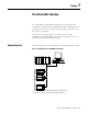
1-2 Pico DeviceNet Interface Structure of the Unit Figure 1.
Pico DeviceNet Interface Use Other Than Intended 1-3 Pico and Pico GFX-70 controllers may not be used to replace safety-relevant control circuits, e.g.: • • • • Furnace, emergency-stop, crane or Two-hand safety controls.
1-4 Pico DeviceNet Interface Publication 1760-UM003A-EN-P - September 2005
Chapter 2 Installation Mounting is the same as for Pico Expansion I/O modules.
2-2 Installation Connect the Power Supply The module operates with a 24V dc supply voltage (see Power Supply specifications on page A-3). Always ensure safe electrical isolation between the extra low voltage (SELV) and the 24V power supply. WARNING +24 V 0V >1A +24 V 0 V Connect DeviceNet A 5-pin DeviceNet plug connects the DeviceNet interface of the device to the DeviceNet field bus. Use a special DeviceNet plug and DeviceNet cable for this connection.
Installation 2-3 All pins of the plug must be connected to ensure safe communication of the 1760-DNET on the fieldbus DeviceNet. This also applies to the 24V bus voltage. The gateway does not participate in communication on the bus if the bus voltage is not available. The Network status LED is OFF in this situation. IMPORTANT Terminating Resistors The first and last node of a DeviceNet network must be terminated by means of a 120 O bus termination resistor.
2-4 Installation Figure 1.
Installation 2-5 • or Flat Cable. The data cable requirements are specified by the ODVA.
2-6 Installation Publication 1760-UM003A-EN-P - September 2005
Chapter 3 Operate the DeviceNet Interface Initial Power On Before you apply power to the DeviceNet Interface, verify that it is properly connected to the power supply, to the bus connectors and to the basic unit. Then, switch on the power supply for the basic unit and the DeviceNet Interface. The LEDs of the 1760-DNET flicker.The device automatically detects the correct baud rate (see Data Transfer Rates – Automatic Baud Rate Recognition on page 2-4).
3-2 Operate the DeviceNet Interface • The basic unit is accessible (password protection not activated). • The basic unit has a valid operating system version. • The basic unit is in STOP mode. + 1. Press the DEL + ALT keys to change to the special menu. PASSWORD... SYSTEM... GB D F E I CONFIGURATOR PASSWORD... 2. Use the cursor keys Í or Ú to change to the Configurator. SYSTEM... GB D F E I CONFIGURATOR 3. Press OK. NET... 4. Select the LINK.... menu with the Pico-GFX units. LINK... 5.
Operate the DeviceNet Interface 3-3 7. Press OK to accept the address. 8. Press ESC to cancel address input. Information about the 4th display line: xxx - xx . xx - xx 222 - 02. 10 - B Hardware version, Index: b Software version, OS version: 2.1 Device identity: 1760-DNET Set the Address with Pico-SOFT With Pico-SOFT, version 3.1 ‹Menu l Online l Configuration of expansion units› With Pico-SOFT, version 4.01 and later ‹Menu l Communication l Configuration l Expansion units l 1760-DNET›.
3-4 Operate the DeviceNet Interface For more information, refer to the programmable controller’s documentation. You can also use various other software packages to modify the MAC ID by sending an explicit message. Do so by using the corresponding service of the DeviceNet object (see DeviceNet Object on page 4-6). LED Status Displays The DeviceNet Interface expansion module is equipped with two indicator LEDs for quick diagnostics. The module monitors itself as well as the DeviceNet communication bus.
Operate the DeviceNet Interface 3-5 Network Status LED (NS) The dual-color LED (GREEN/RED) indicates the status of the DeviceNet communication bus. This function monitors operability and correct operation of the module. Table 3.2 Network Status LED Description Cycle Time of the Pico Basic Unit LED Status Description OFF The module is offline. Either it is performing a DUP_MAC_ID test or power is missing at the device or bus. t GREEN flashing The module is online.
3-6 Operate the DeviceNet Interface Search for the catalog number 1760. IMPORTANT Publication 1760-UM003A-EN-P - September 2005 The Identity Object entry - Major Revision defines the current operating system state of the 1760-DNET communication module. As the device with a newer operating system version can deviate from the EDS description in this point, this entry must be modified accordingly, Identity Object on 4-4.
Chapter 4 DeviceNet Functions Object Model The Pico DeviceNet Interface is based on the Communications Adapter Profile according to the ODVA specifications (Release V2.0). The DeviceNet object model can be used to describe all 1760-DNET functions. The object model reflects the principle of communication at the application layer. This manual deals in the following only with objects relevant for your application. Primary topic is the manufacturer-specific class Pico object. Figure 3.
4-2 DeviceNet Functions Table 3.3 Objects Object Address Class ID (Hex) Instance ID (Hex) Identity Object 01 01 Message Router 02 01 DeviceNet Object 03 01 Connection Object 05 01 ... 04, 04 ...
DeviceNet Functions 4-3 • Message Router Object The Message Router Object (Class ID 02hex) provides access to all classes and instances in the device by means of explicit messages. Connection Objects These objects define messages exchanged via DeviceNet: • DeviceNet Object All devices must support the DeviceNet object (Class ID: 03hex).
4-4 DeviceNet Functions Manufacturer-Specific Objects These objects define device-specific data and functions (Application Objects, Parameter Object, Assembly Object). • Application Objects – Pico Object Application objects (Class ID: 64hex) describe simple applications for automation engineering. They are either predefined in the DeviceNet object library or by the user. Refer to Pico Object on page 4-6.
DeviceNet Functions 4-5 Table 4.4 Attribute IDs of the Identity Object Instance Attribute Access Name ID Description 4 Device version Two bytes are returned when reading the device version. Hardware version, The low byte defines the hardware version, the high byte the operating system version. 1 Read Operating system version Size (byte) 1 5 Read Status This attribute describes the global status of the device.
4-6 DeviceNet Functions DeviceNet Object Object Address Function Access Class ID Instance ID Attribute ID Service Code 03hex 01hex Table 4.6 Table 4.5 The DeviceNet object instance is used to configure the communication module and to define the physical environment. The Service Codes used for the Identity Object also apply in this case. Table 4.
DeviceNet Functions 4-7 supported by this object. The two bytes of attributes 1 and 2 provide the diagnostic data of the device. You can use attribute 3 to access the outputs (S1 to S8) and attribute 4 to access the inputs (R1 of R16) of the basic unit. By using a DeviceNet configuration software (e.g. RSNetworx), you can map these data directly to the corresponding memory areas of a programmable controller. Table 4.
4-8 DeviceNet Functions Table 4.8 Service Code Service Code Value Service Name Description 0Ehex Get_Attribute_Single This service can be used to fetch the value of a selected attribute from the communication module. 10hex Set_Attribute_Single This service can be used to set a selected attribute in the device.
DeviceNet Functions DeviceNet Communication Profile 4-9 DeviceNet is based on a connection-oriented communications model, that is data are exchanged only via the specific connections assigned to the units. DeviceNet stations communicate either by means of I/O messages or explicit messages. I/O Messages I/O messages are used for exchanging high-priority process and application data across the network. Communication between DeviceNet nodes is based on the client/server model, i.e.
4-10 DeviceNet Functions • Time • Image data • Function blocks (counters, timers, analog value comparators,...). General Method of Operation The general method of operation with the 1760-DNET should be presented in the following. The acyclic data transfer is realised with the aid of explicit messages. The function blocks of the Pico basic unit can be addressed via the service code = 32hex. The assigned attribute ID is here used to distinguish between different parameters and functions.
DeviceNet Functions Connection ID = CAN Identifier 7 4-11 Meaning 10 9 8 6 5 4 3 2 1 0 1 0 MAC ID Message ID 1 0 Source MAC ID 0 0 0 Master’s I/O Bit-Strobe Command Message 1 0 Source MAC ID 0 0 1 Reserved for Master’s Use - Use is TBD 1 0 Destination MAC ID 0 1 0 Master’s Change of State or Cyclic Acknowledge Message 1 0 Source MAC ID 0 1 1 Slave’s Explicit/Unconnected Response Messages 1 0 Destination MAC ID 1 0 0 Master’s Explicit Request Messages 1 0
4-12 DeviceNet Functions Description ID (Hex) Length DeviceNet - Byte (Hex) 41C 0 1 2 3 4 5 6 80 01 00 00 00 00 41B 3 80 C1 00 Slave sends a response to the request 41B 8 80 00 B2 C2 05 00 05 04 Master sends remaining PicoLINK byte 6 7 05 09 Byte 2 - Data 1 = 00 Byte 3 - Data 2 = 00 Byte 4 - Data 3 = 00 Byte 5 - Data 4 = 00 Acknowledgement of the slave (Fragmentation protocol) Byte 3 – response = C2 (read successful) Byte 4 – Len = 05 Byte 5 – Index = 00 Byte 6 – Data
Chapter 5 Direct Data Exchange with Pico/GFX (Polled I/O Connection) The DeviceNet master can exchange the following data with the Pico/GFX via the direct cyclic data exchange: TIP The terms “input data” and “output data” are used relative to the point of view of the DeviceNet master. • Write operation – Setting or /resetting of the Pico/GFX inputs (R1 to R16) – Determination of the RUN/STOP mode.
5-2 Direct Data Exchange with Pico/GFX (Polled I/O Connection) Figure 4.6 Input and Output Data Relative to the DeviceNet Master DeviceNet Master Outputs Inputs Write: Output data Inputs R1 – R16 Input data: Mode, S1 to S8 Read: Input data Pico/GFX Outputs S1 – S8 Attribute ID: 3 The cyclic data transfer between DeviceNet master and the Pico DeviceNet Interface slave is provided by the input data byte 0, 1 and 2.
Direct Data Exchange with Pico/GFX (Polled I/O Connection) 5-3 Table 5.11 Byte 0: Operating Mode Pico Identification Bit 7 6 5 4 3 2 1 0 Stop/Run Without Input Delay 0 0 0 1 0 0 0 0/1 With Input Delay 0 0 1 0 0 0 0 0/1 Index for transferring valid data 0 0 0 1 0 1 0 0 0 = status ’0’ 1 = status ’1’ Explanation: Value 14hex = 00010100bin: Byte 0 must always contain this value if data are to be written to the Pico/GFX basic unit via the 1760-DNET gateway.
5-4 Direct Data Exchange with Pico/GFX (Polled I/O Connection) EXAMPLE Value 19hex = 0001 1001bin: S5, S4 and S1 are active Byte 2: not used TIP If control commands and I/O data are used at the same time: • The inputs will retain their previous state until this control command has been executed. • The input bytes will be updated again after the data exchange control command has been terminated.
Direct Data Exchange with Pico/GFX (Polled I/O Connection) 5-5 Table 5.
5-6 Direct Data Exchange with Pico/GFX (Polled I/O Connection) Table 5.15 Byte 1: Setting/resetting of the Pico/GFX inputs R9 to R16 Pico/GFX Bit 7 6 5 4 3 2 1 R9 0/1 R10 0/1 R11 0/1 R12 0/1 R13 0/1 R14 0/1 R15 R16 0 0/1 0/1 0 = status ’0’ 1 = status ’1’ EXAMPLE Value 19hex = 0001 1001bin: Enable R13, R12 and R9. Table 5.
Direct Data Exchange with Pico/GFX (Polled I/O Connection) EXAMPLE 5-7 Value 2Bhex = 0010 1011bin: Enables R6, R4, R2 and R1. TIP If control commands and I/O data are used at the same time: • The inputs will retain their previous state until this control command has been executed. • The input bytes will be updated after the data exchange control command has been executed.
5-8 Direct Data Exchange with Pico/GFX (Polled I/O Connection) Publication 1760-UM003A-EN-P - September 2005
Chapter 6 Application Examples for Pico Control commands can be used to initiate data exchange for special services: • Read/Write Date and Time (page 6-2) • Read/Write Image Data (page 6-4) • Read/write function block data (page 6-20). The DeviceNet master in this case returns to the message transfer protocol of the explicit messages. All parameters are addressed via the Service Code 32hex. The assigned attribute ID is here used to distinguish between different parameters.
6-2 Application Examples for Pico The operating mode of the basic unit must correspond with the status indicated at the LEDs when the various parameters are being set. IMPORTANT The master transmits a control command to initiate data exchange between the communication partners. The slave always returns an answer to this request, which indicates whether data has been exchanged or not. An error code will be returned if data exchange has failed. This code is defined in the ODVA specifications.
Application Examples for Pico 6-3 Table 6.2 Index 0 - Date and Time of Real-Time Clock Byte Content Operand Value (Hex) Master Slave 4 5 Data 3 Day Day (1 to 28; 29, 30, 31; depending on month and year) 0x01 to 0x1Fh 5 6 Data 4 Month 1 to 12 0x01 to 0x0Ch 6 7 Data 5 Year 0 to 99 (corresponds to 2000-2099) 0x00 to 0x63h Table 6.
6-4 Application Examples for Pico Table 6.
Application Examples for Pico 6-5 Table 6.
6-6 Application Examples for Pico Table 6.8 Byte 3 to 4 (master) or Byte 4 to 5 (slave): Data 1 to 2 Data 1 Bit 7 6 5 4 3 2 1 0 A1 0/1 A2 0/1 ... ... A8 Data 2 0/1 Bit 7 6 5 4 3 2 1 0 A9 0/1 A10 0/1 ... A16 ... 0/1 Counters: C1 to C16 The following commands are used to read the logic state of the individual counters C1 to C16. Table 6.
Application Examples for Pico 6-7 Table 6.10 Byte 3 to 4 (master) or Byte 4 to 5 (slave): Data 1 to 2 Data 1 Bit 7 6 5 4 3 2 1 C1 0/1 C2 0/1 … … C8 Data 2 0 0/1 Bit 7 6 5 4 3 2 1 C9 0 0/1 C10 0/1 … … C16 0/1 Text function blocks: D1 – D16 The following commands are used to read the logic state of the individual text function blocks (D markers). Table 6.
6-8 Application Examples for Pico Table 6.12 Byte 3 to 4 (master) or Byte 4 to 5 (slave): Data 1 to 2 Data 1 Bit 7 6 5 4 3 2 1 D1 0 0/1 D2 0/1 ... ... D8 0/1 Data 2 Bit 7 6 5 4 3 2 1 D9 0 0/1 D10 0/1 ... ... D16 0/1 Local inputs: I1 – I16 This command string enables you to read the local inputs of the Pico basic unit. The relevant input word is stored in Intel format. Table 6.
Application Examples for Pico 6-9 Table 6.14 Byte 3 to 4 (master) or Byte 4 to 5 (slave): Data 1 to 2 Data 1 Bit 7 6 5 4 3 2 1 I1 0 0/1 I2 0/1 .. .. I8 0/1 Data 2 Bit 7 6 5 4 3 2 1 I9 0 0/1 I10 0/1 .. .. I16 0/1 Local analog inputs: IA1 – IA4 The analog inputs on the Pico basic unit (I7, I8, I11, I12) can be read directly via DeviceNet. The 16-bit value is transferred in Intel format (Low Byte first). Table 6.
6-10 Application Examples for Pico Example: A voltage signal is present at analog input 1. The required telegrams for reading the analog value are as follows: Table 6.
Application Examples for Pico 6-11 Table 6.17 Telegram Structure Byte Master Meaning Value (hex), sent by Slave Master Slave – C0(3) 01 01 With M marker 86 86 With N marker 87 87 Command rejected 0 1 Len 1 2 Type(1) 2 3 Index2 00 – 0F 00 – 0F 3 4 Data 1 (Low Byte)(2) 00/01 00/01 4–6 5–7 Data 2 – 4 00 00 (1) There are 16 M markers and 16 N markers. The markers are addressed by Type and Index: Use Type to select the M or N marker. Use Index to select the marker number.
6-12 Application Examples for Pico Table 6.19 Telegram Structure Byte Master Meaning Value (hex), sent by Slave Master Slave 88 – Read successful – C2 Command rejected – C0(2) 01 01 M marker 86 86 N marker 87 87 Attribute ID: Read 0 Response: 0 1 Len 1 2 Type 2 3 Index(1) 00 00 3 4 Data 1 (Low Byte) 00 Table 6.20 4 5 Data 2 (Low Byte) 00 Table 6.20 5–6 6–7 Data 3 – 4 00 00 (1) There are 16 M markers and 16 N markers.
Application Examples for Pico 6-13 Table 6.21 The N Markers are Read Byte Meaning Master Value (hex), sent by Slave Master Slave 88 – Read successful – C2 Command rejected – C0(1) 01 01 N marker 87 87 Attribute ID: Read 0 Response: 0 1 Len 1 2 Type 2 3 Index 00 00 3 4 Data 1 (Low Byte) 00 04 4 5 Data 2 (Low Byte) 00 84 5–6 6–7 Data 3 – 4 00 00 (1) Possible causes a page 49 The markers N3, N11 and N16 are set.
6-14 Application Examples for Pico Table 6.23 Byte 3 (master) or byte 4 (slave): Data 1 Data 1 Bit 7 6 5 4 3 2 1 O1 0 0/1 O2 0/1 O3 0/1 O4 0/1 ... ... ... ... ... Local P buttons: P1 – P4 The local P buttons are the display cursor buttons of the Pico basic unit. You can scan the buttons in both RUN and STOP mode. IMPORTANT Ensure that the P buttons are also activated via the System menu (in the basic unit). Only one byte has to be transferred for the P buttons. Table 6.
Application Examples for Pico 6-15 Table 6.25 Byte 3 (master) or byte 4 (slave): Data 1 Data 1 Bit 7 6 5 4 3 2 1 P1 0 0/1 P2 0/1 P3 0/1 P4 0/1 – 0 – 0 – 0 – 0 Example: Data 1 = 2hex l P3 is active. Local outputs: Q1 – Q8 The local outputs can be read directly via the DeviceNet fieldbus. Table 6.
6-16 Application Examples for Pico Table 6.27 Byte 4: Data 1 Q2 0/1 .. .. Q8 0/1 Example: Data 1 = 52hex l Q2, Q5 and Q7 are active. Inputs/outputs of PicoLink: R1 – R16/S1 – S8 This service allows you to read the local R and S data and the data of the NET stations (1 – 8) transferred via PicoLink, again from the relevant Pico image. Table 6.
Application Examples for Pico 6-17 Table 6.29 Byte 3 to 4 (master) or Byte 4 to 5 (slave): Data 1 to 2 R8 S8 0/1 Data 2 Bit R9 – R10 – ... – R16 – 7 6 5 4 3 2 1 0 0/1 0/1 ... 0/1 Timers: T1 – T16 The following commands are used to read the logic state of the individual timers T1 - T16. Table 6.
6-18 Application Examples for Pico Table 6.31 Byte 3 to 4 (master) or Byte 4 to 5 (slave): Data 1 to 2 T10 0/1 ... ... T16 0/1 Year time switch: Y1 – Y8 The following commands are used to read the logic state of the individual year time switches. Table 6.
Application Examples for Pico 6-19 Master reset: Z1 – Z3 Table 6.34 Telegram Structure Byte Master Meaning Value (hex), sent by Slave Master Slave 88 – Read successful – C2 Command rejected – C0(1) Attribute ID: Read 0 Response: 0 1 Len 01 01 1 2 Type 93 93 2 3 Index 00 00 3 4 Data 1 (Low Byte) 00 Table 6.35 4–6 5–7 Data 2 – 4 00 00 (1) Possible causes page 6-34 = Table 6.
6-20 Application Examples for Pico Table 6.36 Telegram Structure Byte Master Meaning Value (hex), sent by Slave Command rejected Master Slave – C0(1) 0 1 Len 01 01 1 2 Type 90 90 2 3 Index 00 00 3 4 Data 1 (Low Byte) 00 Table 6.37 4–6 5–7 Data 2 – 4 00 00 (1) Possible causes page 6-34 Table 6.
Application Examples for Pico 6-21 • The maximum data length is 4 bytes. All values must be transferred in hexadecimal format. Overview Table 6.
6-22 Application Examples for Pico Table 6.40 Operand overview Index (hex) Operand Read 00 Parameters Table 6.41 x 01 Control byte Table 6.
Application Examples for Pico 6-23 Example: Data 1 (Byte 4) = 0xA3, Data 2 (Byte 5) = 0x03 l Resulting 16-bit value = 03A3hex Meaning: HY, OS, F2, F1 are assigned a constant; I1, I2 are assigned to a variable such as I7, I8 C2...etc., appears in the Parameter menu; The output of the analog value comparator is active for as long as the comparison (I1 x F1) + OS = (I2 x F2) + HY is fulfilled. Table 6.
6-24 Application Examples for Pico Table 6.44 Operand overview Index (hex) Operand Read 00 Parameters Table 6.45 x 01 Control byte Table 6.46 02 03 Write x Process variable S1 (1) x c(2) Counter setpoint 2 S2(1) x c(2) (1) A 16-bit value is transferred in data bytes Data 1 – Data 2. It should be remembered that Data 1 is the low byte and Data 2 the high byte. (2) The value can only be written if it is assigned to a constant in the program. Table 6.
Application Examples for Pico 6-25 Table 6.47 C3 Value to Read Byte Meaning Master Value (hex), sent by Slave Master Slave Command: Read 89 – 0 Response: read successful – C2 0 1 Type 8F 8F 1 2 Instance 02 02 2 3 Index 02 02 3 4 Data1 00 12 4 5 Data 2 00 03 5 6 Data 3 00 00 6 7 Data 4 00 00 Explanation: Data 1 = 12 Data 2 = 03 l resulting 16-bit value = 0312hex = 786dec Counter status = 786 Operating hours counters: O1 – O4 Table 6.
6-26 Application Examples for Pico Table 6.48 Telegram Structure Byte Meaning Value (hex), sent by Master Slave Master Slave 1 2 Instance(1) 00 – 03 00 – 03 2 3 Index Table 6.49 Table 6.49 3–6 4–7 Data 1 – 4 depending on index,Table 6.50 depending on index,Table 6.50 (1) Pico provides 4 operating hours counters O1 to O4. These can be addressed using the instance (0 – 3). (2) Possible causes page 6-34 Table 6.
Application Examples for Pico 6-27 Table 6.51 Index 01 – Control byte Data 1 Bit FB output 7 6 5 4 3 2 1 0 – – – – – RE(1) EN(2) Q1(3) (1) Reset, the timing relay is reset (reset coil) (2) Enable, the timing relay is started (trigger coil) (3) Switch contact Example: Index 02/03 Transferred values:Data 1 0x21 Data 2 0x23 Data 3 0x40 Data 4 0x00 Resulting value: 00402321hex = 4203297dec Timing relays: T1 – T16 Table 6.
6-28 Application Examples for Pico Table 6.53 Operand overview Index (hex) Operand Read Write 00 Parameters Table 6.54 x 01 Control byte Table 6.55 x 02 Actual value 1 T x c(2) 03 Time setpoint 1 S1(1) x c(2) 04 Time setpoint 2 S2(1) x c(2) (1) A 16-bit value is transferred in data bytes Data 1 – Data 2. It should be remembered that Data 1 is the low byte and Data 2 the high byte. (2) The value can only be written if it is assigned to a constant in the program. Table 6.
Application Examples for Pico 6-29 Meaning: The values appear in the Parameter menu. The time is used in the impulse transmitter mode with the Second time base. The time setpoint S1 is assigned a constant and the time setpoint S2 is assigned a variable such as I7, I8 C2...etc. Table 6.
6-30 Application Examples for Pico Year time switch: Y1 – Y8 Table 6.58 Telegram Structure Byte Master Meaning Slave Value (hex), sent by Master Slave Read 89 – Write 8D – Read successful – C2 Write successful – C1 Command rejected – C0(2) Attribute ID 0 Response: 0 1 Type A2 A2 1 2 Instance(1) 00 – 07 00 – 07 2 3 Index Table 6.59 Table 6.59 3–6 4–7 Data 1 – 4 depending on index,Table 6.60 depending on index,Table 6.
Application Examples for Pico 6-31 Table 6.59 Operand overview Index (hex) Operand Read Write Channel D x c(1) 41 Time point ON x c(1) 42 Time point OFF x c(1) (1) The value can only be written if it is assigned to a constant in the program. In the data bytes Data 1 – Data 3 the switching points are transferred. Table 6.
6-32 Application Examples for Pico Index = 0x11 Data 1 = 0x15 Data 2 = 0x04 Data 3 = 0x04 The year time switch channel B should be switched off on the 05.11.2012. Index = 0x22 Data 1 = 0x05 Data 2 = 0x0B Data 3 = 0x0C 7-day time switch: Ö1 – Ö8 Table 6.
Application Examples for Pico 6-33 Table 6.63 Operand overview Index (hex) Operand Read 00 Parameters Table 6.64 x 01 Control byte Table 6.
6-34 Application Examples for Pico Meaning: The values of the 7-day timer switch WH.. of channel A and B appear in the parameter menu. Table 6.65 Index 01 – Control byte Data 1 Bit FB output 7 6 5 4 3 2 1 0 – – – – – – – Q1(1) (1) Status 1 if count condition is fulfilled. Channel A, index 11/12/13 Index 0x11 channel A day on/off Data 1 (Byte 4) – day on Data 2 (Byte 5) – day off 0x01 = Sunday ... 0x07 = Saturday If the channel is not used the 16 bit value is equal to 0x00.
Application Examples for Pico 6-35 Table 6.67 Error codes Error code Description 0x01 An unknown telegram has been sent. 0x02 An unknown object has been sent. 0x03 An unknown command has been sent. 0x04 An invalid instance has been sent. 0x05 An invalid parameter set has been used. 0x06 An attempt has been made to write a variable which is not a constant. 0x0C The device is in an invalid device mode. STOP l RUN or RUN l STOP 0x0D An invalid display access occurs.
6-36 Application Examples for Pico Publication 1760-UM003A-EN-P - September 2005
Chapter 7 Pico GFX Control Commands Control commands can be used to initiate data exchange for special services: • Read/write date and time (page 7-2) • Read/write image data (page 7-7) • Read/write function block data (page 7-20) The DeviceNet master in this case falls back upon the message transfer protocol of the explicit messages. All parameters are addressed via the Service Code 32hex. The assigned attribute ID is here used to distinguish between different parameters.
7-2 Pico GFX Control Commands TIP The operating mode of the basic unit must correspond with the status indicated at the LEDs when the various parameters are being set. The master transmits a control command to initiate data exchange between the communication partners. The slave always returns an answer to this request, which indicates whether data has been exchanged or not. An error code will be returned if data exchange has failed. This code is precisely defined in the ODVA specifications.
Pico GFX Control Commands 7-3 Table 6.68 Telegram Structure Byte Meaning Master Slave Value (hex), sent by Master Slave Read 93 – Write B3 – Read successful – C2 Write successful – C1 Command rejected – C0 Attribute ID 0 Answer 0 1 Len 05 05 1 2 Index 00 00 2–6 3–7 Data 1 – 5 Read operation 00 Table 6.69 Write operation Table 6.69 00 Table 6.
7-4 Pico GFX Control Commands Winter/summer time, DST Table 6.70 Telegram Structure Byte Meaning Master Slave Value (hex), sent by Master Slave Read 93 – Write B3 – Read successful – C2 Write successful – C1 Command rejected – C0 05 05 01: Summer/Winter time Table 6.71 Table 6.71 02: Winter time (to the “Area” = rule”)(1) Table 6.72 Table 6.72 Read operation 00 depending on index, Table 6.71 and Table 6.72 Write operation depending on index, Table 6.71 and Table 6.
Pico GFX Control Commands 7-5 Table 6.71 Index 01 – Summer/Winter time switchover Byte Content Master Slave 2 3 Data 1 Value (hex) Area None 00 Manual 01 Automatic EU 02 Automatic GB 03 Automatic US 04 Rule(1) 05 00 – 3B for “Area” = “manual”: 3 4 Data 2 Set summer time day (1 to 28, 29, 30, 31 depending on month and year).
7-6 Pico GFX Control Commands Table 6.
Pico GFX Control Commands Read/write image data 7-7 Overview Table 6.75 Operands Meaning Read/Write Command Page (hex) IA1 – IA4 “Local analog inputs: IA1 – IA4“ read 02 7 ID1 – ID16 “Local diagnostics: ID1 – ID16“ read 03 9 IW0 “Read local inputs: IW0“ read 01 10 IW1 – IW8 “Inputs of the network station: IW1 – IW8“ read 01 11 M... “Marker: M..
7-8 Pico GFX Control Commands Table 6.76 Telegram Structure Byte Meaning Master Slave 0 1 1 Value (hex), sent by Master Slave Len 02 02 2 Type 02 02 2 3 Index 01 – 04(1) 01 – 04(1) 3 4 Data 1 (Low Byte) 00 a example on page 7-8 4 5 Data 2 (High Byte) 00 5–6 6–7 Data 3 – 4 00 00 (1) 01 = Analog input I7 02 = Analog input I8 03 = Analog input I11 04 = Analog input I12 Example A voltage signal is present at analog input 1.
Pico GFX Control Commands 7-9 Local diagnostics: ID1 – ID16 The local diagnostics (ID1 – ID8) bytes indicate the status of the individual NET stations. The connection to the remote station (only GFX) is indicated via ID9. Table 6.78 Telegram Structure Byte Meaning Master Value (hex), sent by Slave Master Slave 91 – Read successful – C2 Command rejected – C0 Attribute ID: Read 0 Response: 0 1 Len 02 02 1 2 Type 03 03 2 3 Index 00 00 3 4 Data 1 (Low Byte) 00 Table 6.
7-10 Pico GFX Control Commands Example Data 1 = F8, Data 2 = FF l In the Pico-NET network, the three stations are present with the NET IDs 1, 2, 3 Read local inputs: IW0 This command string enables you to read the local inputs of the Pico GFX. The relevant input word is stored in Intel format. Table 6.
Pico GFX Control Commands 7-11 Table 6.82 Read Local Inputs IW0 Byte Meaning Master Value (hex), sent by Slave Master Slave Attribute ID: Read 91 – 0 Response: Read successful – C2 0 1 Len 02 02 1 2 Type 01 01 2 3 Index 00 00 3 4 Data 1 00 C4 4 5 Data 2 00 02 5 6 Data 3 00 00 6 7 Data 4 00 00 All values must be transferred as hexadecimal values. TIP The values Data 1 = C4 and Data 2 = 02 indicate that the inputs I8, I7, I3 and I10 have been set to 1.
7-12 Pico GFX Control Commands Table 6.83 Telegram Structure Byte Meaning Master Slave 1 2 2 Value (hex), sent by Master Slave Type 01 01 3 Index 01 – 08(1) 01 – 08(1) 3 4 Data 1 (Low Byte) 00 Table 6.81 4 5 Data 2 (High Byte) 00 5–6 6–7 Data 3 – 4 00 00 (1) Corresponds to address of network station Marker: M.. Table 6.
Pico GFX Control Commands 7-13 Table 6.85 Byte 0 to 2 (master) or: Byte 1 to 3 slave: Len, Type, Index Operand Len Type Index Marker bit M1…M96 01hex 0Bhex 01 to 60hex Marker byte MB1…MB96 01hex 0Chex 01 to 60hex Marker word MW1…MW96 02hex 0Dhex 01 to 60hex Marker double word MD1…MD96 04hex 0Ehex 01 to 60hex If required, refer to the more detailed description of the marker allocation in the Pico GFX manual.
7-14 Pico GFX Control Commands Example 1: Set/reset market bit Marker bit 62 should be set or reset. Write a “1” to set or a “0” to reset the marker bit in the least significant bit of data byte “Data 1”. Example 2: Write marker word Table 6.
Pico GFX Control Commands 7-15 Local P buttons: P1 – P4 The local P buttons are the display cursor buttons of the Pico GFX basic unit. You can scan the buttons in both RUN and STOP mode. Ensure that the P buttons are also activated via the SYSTEM menu (in the basic unit). TIP Only one byte has to be transferred for the P buttons. Table 6.
7-16 Pico GFX Control Commands Local analog output: QA1 The commands provided can be used to access the local analog output of the Pico GFX or GFX basic unit. When writing to the analog output (only possible from Pico GFX, device version 04) the value will only be output if the respective device is in RUN mode and if the respective image is not written by the actual program, a section “Read/write image data”on page 7. Table 6.
Pico GFX Control Commands 7-17 Local outputs: QW0/ outputs of the network station: QW1 – QW8 The local outputs can be read directly via DeviceNet, and from Pico GFX version 04 they can also be written. However, the outputs are only switched externally if the device is in Run mode and the addressed output is not being used in the circuit diagram. Refer to Read/write image data on page 7-7. Table 6.
7-18 Pico GFX Control Commands Table 6.93 Byte 4: Data Q6 0 Q7 0 Q8 0 Inputs/outputs of PicoLink: RW/SW This service allows you to read the local R and S data and the data of the NET stations (1 – 8) transferred via PicoLink, again from the relevant Pico GFX image. Table 6.
Pico GFX Control Commands 7-19 Table 6.95 Byte 4 to 5: Data 1 to 2 R6 S6 R7 S7 R8 S8 0/1 0/1 0/1 Data 2 Bit R9 – R10 – R11 – R12 – R13 – R14 – R15 – R16 – 7 6 5 4 3 2 1 0 0/1 0/1 0/1 0/1 0/1 0/1 0/1 0/1 Receive data network: RN1 – RN32/ Send data network: SN1 – SN32 PicoNET allows a point-to-point connection to be implemented between the individual NET stations. The RN and SN data are used for the data exchange (see publication 1760-UM002).
7-20 Pico GFX Control Commands Table 6.96 Byte Master Meaning Value (hex), sent by Slave Master Slave For SN1 – SN32: 0A For SN1 – SN32: 0A 2 3 Index 01 – 08(1) 01 – 08(1) 3–6 4–7 Data 1 – 4 00 Table 6.97 (1) Corresponds to NET-ID Table 6.97 Byte 4 to 7: Data 1 to 4 Data 1 RN1 Bit 7 6 5 SN1 4 3 2 ... 0/1 RN8 SN8 Data 2 RN9 0/1 Bit 7 6 5 4 3 2 1 SN9 0 0/1 .... ... RN16 SN16 Data 3 RN17 0/1 Bit 7 6 5 4 3 2 1 SN17 0 0/1 ... ...
Pico GFX Control Commands 7-21 Overview Table 6.
7-22 Pico GFX Control Commands Analog value comparator: A01 – A32 Table 6.99 Telegram Structure Byte Master Meaning Slave Value (hex), sent by Master Slave Read 92 – Write B2 – Read successful – C2 Write successful – C1 Command rejected – C0 Attribute ID 0 Response: 0 1 Type 11 11 1 2 Instance 01 – 20 01 – 20 2 3 Index Table 6.100 Table 6.100 3–6 4–7 Data 1 – 4 00 depending on index, Table 6.101 and 6.102 Table 6.
Pico GFX Control Commands 7-23 The data for index 2 to 7 is transferred as a 32-bit value in Intel format (Data 1 – Low Byte to Data 4 – High Byte). TIP Table 6.101 Index 0 – Bit IO Bit FB output Data 3 7 6 5 4 3 2 – – – – – – 1 CY 0 (1) Q1(2) (1) Status 1 if the value range is exceeded (2) Status 1 if the condition is fulfilled (e.g. I1 < I2 with LT mode) Table 6.
7-24 Pico GFX Control Commands Table 6.103 Telegram Structure Byte Meaning Value (hex), sent by Master Slave Master Slave Table 6.104 Table 6.104 Read operation 00 depending on index, Table 6.105 and 6.106 Write operation depending on index, Table 6.105 and 6.106 00 2 3 Index 3–6 4–7 Data 1 – 4 Table 6.104 Operand overview Index (hex) Operand read write 00 Bit IO, Table 6.105 x 01 Mode, Table 6.
Pico GFX Control Commands 7-25 Table 6.106 Index 1 - Mode Data 1 (hex) 00 ADD Add (I1 + I2 = QV) 01 SUB Subtract (I1 – I2 = QV) 02 MUL Multiply (I1 x I2 = QV) 03 DIV Divide (I1 : I2 = QV) Block Compare: BC01 – BC32 Table 6.
7-26 Pico GFX Control Commands Table 6.108 Operand overview Index (hex) Operand read write 00 Bit IO, Table 6.109 x 01 Mode, Table 6.110 x 02 Source range 1 I1 x c(1) 03 Target range 2 I2 x c(1) 04 Number of elements to compare: 8 (max. 192 bytes) NO x c(1) (1) The value can only be written if it is assigned to a constant in the program. The data for index 2 to 4 is transferred as a 32-bit value in Intel format (Data 1 – Low Byte to Data 4 – High Byte). TIP Table 6.
Pico GFX Control Commands 7-27 Block Transfer: BT01 – BT32 Table 6.111 Telegram Structure Byte Meaning Maste r Slav e Value (hex), sent by Master Slave Read 92 – Write B2 – Read successful – C2 Write successful – C1 Command rejected – C0 Attribute ID 0 Response: 0 1 Type 26 26 1 2 Instance 01 – 20 01 – 20 2 3 Index Table 6.112 Table 6.112 3–6 4–7 Data 1 – 4 Read operation 00 depending on index, Table 6.113, 6.114 Write operation depending on index, Table 6.
7-28 Pico GFX Control Commands Table 6.113 Index 0 – Bit IO Bit 7 6 5 4 3 2 1 0 FB input Data 1 – – – – – – – T(3) FB output Data 3 – – – – – E3(1) E2(2) E1(4) (1) Status 1 if the number of elements exceeds the source or target range. (2) Status 1 if the source and target range overlap. (3) Transfer of the source address specified at I1 to the target address specified at I2 on rising edge.
Pico GFX Control Commands 7-29 Table 6.115 Telegram Structure Byte Meaning Master Slave 3–6 4–7 Value (hex), sent by Master Slave Read operation 00 depending on index, Table 6.117 and 6.118 Write operation depending on index, Table 6.117 and 6.118 00 Data 1 – 4 Table 6.116 Operand overview Index (hex) Operand read write 00 Bit IO, Table 6.117 x 01 Mode, Table 6.
7-30 Pico GFX Control Commands Table 6.118 Index 1 - Mode Data 1 (hex) 01 OR Or sequence 02 XOR Exclusive Or sequence 03 NET Inverts the individual bits of the value at I1. The inverted value is represented as a signed decimal value. Counter: C01 – C32 Table 6.
Pico GFX Control Commands 7-31 Table 6.120 Operand overview Index Operand (hex) Value read write In integer range from –2147483648 to +2147483647 x c(1) x c(1) c(1) 02 Upper setpoint SH 03 Lower setpoint SL 04 Preset actual value SV x 05 Actual value in Run mode QV x (1) The value can only be written if it is assigned to a constant in the program. TIP The data for index 2 to 5 is transferred as a 32-bit value in Intel format (Data 1 – Low Byte to Data 4 – High Byte). Table 6.
7-32 Pico GFX Control Commands Frequency counters: CF01 – CF04 Table 6.122 Telegram Structure Byte Meaning Master Slave Value (hex), sent by Master Slave Read 92 – Write B2 – Read successful – C2 Write successful – C1 Command rejected – C0 Attribute ID 0 Response: 0 1 Type 15 15 1 2 Instance 01 – 04 01 – 04 2 3 Index Table 6.123 Table 6.123 3–6 4–7 Data 1 – 4 Read operation 00 depending on index,Table 6.124 Write operation depending on index,6.124 00 Table 6.
Pico GFX Control Commands 7-33 Table 6.124 Index 0 – Bit IO Bit 7 6 5 4 3 2 1 0 FB input Data 1 – – – – – – – EN(3) FB output Data 3 – – – – – ZE(1) FB(2) OF(4) (1) Zero: Status 1 if the value of the function block output QV (the counter status) equals zero (2) Fall below: Status 1 if the actual value F lower setpoint (3) Counter enable (4) Overflow: Status 1 if the actual value f upper setpoint High-speed counter: CH01 – CH04 Table 6.
7-34 Pico GFX Control Commands Table 6.126 Operand overview Inde Operand x (hex) Value read write 00 Bit IO Table 6.127 x 01 Mode/Parameter – – – 02 Upper setpoint SH x c(1) 03 Lower setpoint SL In integer range from –2147483648 to +2147483647 x c1 04 Preset actual value SV x c1 05 Actual value in Run mode QV x (1) The value can only be written if it is assigned to a constant in the program.
Pico GFX Control Commands 7-35 Incremental encoder counters: CI01 – CI02 Table 6.128 Telegram Structure Byte Meaning Value (hex), sent by Master Slave Master Slave Read 92 – Write B2 – Read successful – C2 Write successful – C1 Command rejected – C0 Attribute ID 0 Response: 0 1 Type 17 17 1 2 Instance 01 – 02 01 – 02 2 3 Index Table 6.129 Table 6.129 3–6 4–7 Data 1 – 4 Read operation 00 depending on index,Table 6.
7-36 Pico GFX Control Commands (1) The value can only be written if it is assigned to a constant in the program. TIP The data for index 2 to 5 is transferred as a 32-bit value in Intel format (Data 1 – Low Byte to Data 4 – High Byte). Table 6.
Pico GFX Control Commands 7-37 Table 6.131 Telegram Structure Byte Meaning Master Slave 3–6 4–7 Value (hex), sent by Master Slave Read operation 00 depending on index,Table 6.133 Write operation depending on index, Table 6.133 00 Data 1 – 4 Table 6.132 Operand Overview Index (hex) Operand read write 00 Bit IO, Table 6.
7-38 Pico GFX Control Commands Text output function block: D01 – D32 Table 6.134 Telegram Structure Byte Meaning Master Slav e Value (hex), sent by Master Slave Read 92 – Write B2 – Read successful – C2 Write successful – C1 Command rejected – C0 Attribute ID 0 Response: 0 1 Type 19 19 1 2 Instance 01 – 20 01 – 20 2 3 Index Table 6.135 Table 6.135 3–6 4–7 Data 1 – 4 Read operation 00 depending on index,Table 6.136 Write operation depending on index, Table 6.
Pico GFX Control Commands 7-39 Table 6.
7-40 Pico GFX Control Commands Table 6.136 Index 0 – Bit IO Bit 7 6 5 4 3 2 1 0 FB input Data 1 – – – – – – – EN(1) FB output Data 3 – – – – – – – Q1(2) (1) Text function block enable (2) Status 1, text function block is active Data block: DB01 – DB32 Table 6.
Pico GFX Control Commands 7-41 Table 6.138 Operand overview Index (hex) Operand read 00 Bit IO, Table 6.139 x 01 Mode/Parameter – – 02 I1 Input value: value that is transferred to the QV output when the FB is triggered. x c(1) 03 Output value x QV write (1) The value can only be written if it is assigned to a constant in the program. The data for index 2 and 3 is transferred as a 32-bit value in Intel format (Data 1 – Low Byte to Data 4 – High Byte). TIP Table 6.
7-42 Pico GFX Control Commands Table 6.140 Telegram Structure Byte Meaning Master Slave Value (hex), sent by Master Slave Write successful – C1 Command rejected – C0 0 1 Type 27 27 1 2 Instance 01 – 20 01 – 20 2 3 Index Table 6.141 Table 6.141 3–6 4–7 Data 1 – 4 Read operation 00 depending on index, Table 6.142, 6.143 Write operation depending on index, Table 6.142, 6.143 Table 6.141 Operand overview Index (hex) Operand read write 00 Bit IO, Table 6.
Pico GFX Control Commands 7-43 The data for index 2 to 9 is transferred as a 32-bit value in Intel format (Data 1 – Low Byte .. Data 2 High Byte). TIP Table 6.
7-44 Pico GFX Control Commands Table 6.144 Telegram Structure Byte Meaning Value (hex), sent by Master Slave Master Slave Write successful – C1 Command rejected – C0 0 1 Type 28 28 1 2 Instance 01 – 20 01 – 20 2 3 Index Table 6.145 Table 6.145 3–6 4–7 Data 1 – 4 Read operation 00 depending on index,Table 6.146 Write operation depending on index,Table 6.146 00 Table 6.145 Operand overview Index Operand (hex) read write 00 Bit IO, Table 6.
Pico GFX Control Commands 7-45 Receipt of network data: GT01 – GT32 Table 6.147 Telegram Structure Byte Meaning Master Value (hex), sent by Slave Master Slave 92 – Read successful – C2 Command rejected – C0 Attribute ID: Read 0 Response: 0 1 Type 1B 1B 1 2 Instance 01 – 20 01 – 20 2 3 Index Table 6.148 Table 6.148 3–6 4–7 Data 1 – 4 00 depending on index, Table 6.149 and 6.150 Table 6.148 Operand overview Index (hex) Operand read 00 Bit IO, Table 6.
7-46 Pico GFX Control Commands Table 6.150 Index 1 – Mode/Parameters (designation of PUT FB with data to be received) Mode Data 1 Parameters Data 3 NET-ID(1) 0 NET-ID 1 .. .. 7 NET-ID 8 Instance(2) 0 PT01 .. .. 31 PT32 (1) Number of station sending the value. Possible station numbers: 01 to 08 (2) Send FB (e.g. PT 20) of the sending NET station. Possible station numbers: 01 – 32 7-day time switch: HW01 – HW32 Table 6.
Pico GFX Control Commands 7-47 Table 6.152 Operand overview Index (hex) Operand read 00 Bit IO 01 Mode/Parameter 02 Parameters Table 6.153 write x – Table 6.154 – x Channel A 03 Channel B 04 Channel C 05 Channel D Table 6.153 Index 0 – Bit IO Bit FB output Data 3 7 6 5 4 3 2 1 0 – – – – – – – Q(1) (1) Status 1 if the switch-on condition is fulfilled. The data in the following table is shown in the Motorola format although it is actually transferred in Intel format.
7-48 Pico GFX Control Commands Table 6.155 Byte Meaning Value (hex), sent by Master Slave Attribute ID: Read 92 – Response: Read successful – C2 1 Type 1C 1C 2 Instance 13 13 3 Index 02 02 4 Data 1 00 62 5 Data 2 00 0B 6 Data 3 00 7B 7 Data 4 00 25 0 Table 6.156 Switch-on Time Bit 7 6 5 4 3 2 1 0 Date 2 = 0Bhex ON 0 0 0 7 6 5 4 3 2 1 0 0 0 0 1 0 Date 1 = 62hex 0 1 0 Weekday(1) 1 1 0 1 Hour(2) 1 Minute(3) (1) Weekday = 01hex ..
Pico GFX Control Commands 7-49 Year time switch: HY01 – HY32 Table 6.158 Telegram Structure Byte Master Meaning Value (hex), sent by Slave Master Slave Attribute ID: Read 92 0 – Response: Read successful – C2 Command rejected – C0 0 1 Type 1D 1D 1 2 Instance 01 – 20 01 – 20 2 3 Index Table 6.159 Table 6.159 3–6 4–7 Data 1 – 4 00 depending on index,Table 6.160 Table 6.159 Operand overview Index (hex) Operand 00 Bit IO 01 Mode/Parameter 02 Parameters read Table 6.
7-50 Pico GFX Control Commands Table 6.161 Index 2 – 5, Parameter channels A – D Bit 7 6 5 4 3 2 1 0 7 Date 2 ON 5 4 3 2 1 0 Date 1 y6(1) y5 y4 y3 y2 y1 y0 m3(2) m2 m1 m0 d4(3) d3 d2 d1 d0 Year Bit 6 7 Month 6 5 4 3 2 1 0 7 Date 4 OFF y6 Day 6 5 4 3 2 1 0 Date 3 y5 y4 y3 y2 y1 y0 m3 Year m2 m1 m0 d4 Month d3 d2 d1 d0 Day (1) y6 ... y0: Year (0: 2000 .. 99: 2099) (2) m3 ... m0: Month (1 .. 12) (3) d4 ... d0: Day (1 ..
Pico GFX Control Commands 7-51 Table 6.164 Resulting Telegram Byte Meaning Value (hex), sent by Master Slave Attribute ID: Write B2 – Response: Write successful – C1 1 Type 1D 1D 2 Instance 0E 0E 3 Index 02 02 4 Data 1 8E 00 5 Data 2 06 00 6 Data 3 43 00 7 Data 4 19 00 0 Value scaling: LS01 – LS32 Table 6.
7-52 Pico GFX Control Commands Table 6.166 Operand overview Index (hex) Operand read write 00 Bit IO, Table 6.
Pico GFX Control Commands 7-53 Table 6.168 Telegram Structure Byte Meaning Value (hex), sent by Master Slave Master Slave 0 1 Type 0F 0F 1 2 Instance 01 – 20 01 – 20 2 3 Index Bit IO 00 00 Mode 01 01 Data 1 – 4 00 depending on index, Table 6.169, 6.170 3–6 4–7 Table 6.169 Index 0 – Bit IO Bit 7 6 5 4 3 2 1 0 FB input Data 1 – – – – – – – T(1) FB output Data 3 – – – – – – – Q1(2) (1) Trigger coil.
7-54 Pico GFX Control Commands Table 6.171 Telegram Structure Byte Meaning Value (hex), sent by Master Slave 0 Master Slave Read successful – C2 Write successful – C1 Command rejected – C0 Response: 0 1 Type A2 A2 1 2 Instance 01 – 20 01 – 20 2 3 Index Table 6.172 Table 6.172 3–6 4–7 Data 1 – 4 Read operation 00 depending on index, Table 6.173, 6.174 Write operation depending on index, Table 6.173, 6.174 00 Table 6.
Pico GFX Control Commands 7-55 Table 6.174 Index 1 - Mode Data 1 (hex) 00 BCD Converts a BCD coded decimal value to an integer value. 01 BIN Converts an integer value to a BCD coded decimal value. Hours-run meters: OT01 – OT04 h Further information is available in the S40 Application Note AN27K21g.exe “Pico GFX-DP Data Handling Function Block for PS416 and PS4-341”. Telegram structure Table 6.
7-56 Pico GFX Control Commands Table 6.176 Operand overview Index (hex) Operand read write 00 Bit IO, Table 6.177 x 01 Mode/Parameter – – 02 Upper threshold value I1 x c(1) 03 Actual value of operating hours counter QV x (1) The value can only be written if it is assigned to a constant in the program. Table 6.
Pico GFX Control Commands 7-57 Table 6.178 Telegram Structure Byte Meaning Master Slave 1 2 2 3–6 Value (hex), sent by Master Slave Instance 01 – 20 01 – 20 3 Index Table 6.179 Table 6.179 4–7 Data 1 – 4 00 depending on index,Table 6.180 Table 6.179 Operand overview Index (hex) Operand read 00 Bit IO, Table 6.
7-58 Pico GFX Control Commands Pulse width modulation: PW01 – PW02 Table 6.181 Telegram Structure Byte Meaning Master Slave Value (hex), sent by Master Slave Read 92 – Write B2 – Read successful – C2 Write successful – C1 Command rejected – C0 Attribute ID 0 Response: 0 1 Type 2B 2B 1 2 Instance 01 – 02 01 – 02 2 3 Index Table 6.182 Table 6.182 3–6 4–7 Data 1 – 4 Read operation 00 depending on index,Table 6.183 Write operation depending on index,Table 6.
Pico GFX Control Commands 7-59 Table 6.183 Index 0 – Bit IO Bit 7 6 5 4 3 2 1 0 FB input Data 1 – – – – – – – EN(1) FB output Data 3 – – – – – – – E1(2) (1) Activates the function block on status 1. (2) Status 1 if below the minimum on duration or minimum off duration Synchronize clock function block: SC01 Table 6.
7-60 Pico GFX Control Commands (1) Trigger coil. If the coil is triggered (rising edge), the current date, weekday and time of the sending station are automatically sent to the NET network. (2) Status 1 if the trigger coil SC01T_ is also 1. Set cycle time function block: ST01 Table 6.
Pico GFX Control Commands 7-61 Table 6.189 Index 0 – Bit IO Bit FB output Data 3 7 6 5 4 3 2 1 0 – – – – – – – EN(1) (1) Activates the function block on status 1. Timing relays: T01 – T32 Table 6.190 Telegram Structure Byte Meaning Master Slave Value (hex), sent by Master Slave Read 92 – Write B2 – Read successful – C2 Write successful – C1 Command rejected – C0 Attribute ID 0 Response: 0 1 Type 21 21 1 2 Instance 01 – 20 01 – 20 2 3 Index Table 6.
7-62 Pico GFX Control Commands Table 6.191 Operand overview Index (hex) Operand read write 02 Setpoint 1: Time setpoint 1 I1 x c(1) 03 Setpoint 2: Time setpoint 2 (with timing relay with 2 setpoints) I2 x c(1) 04 Actual value: Time elapsed in Run mode QV x (1) The value can only be written if it is assigned to a constant in the program. TIP The data for index 2 to 4 is transferred as a 32-bit value in Intel format (Data 1 – Low Byte to Data 4 – High Byte). Table 6.
Pico GFX Control Commands 7-63 Table 6.193 Index 1 - Mode/Parameters Mode Parameters Data 1 Mode 0 On-delayed, 1 On-delayed with random setpoint 2 off-delayed.
7-64 Pico GFX Control Commands Table 6.194 Telegram Structure Byte Meaning Value (hex), sent by Master Slave 3–6 4–7 Master Slave Read operation 00 depending on index,Table 6.196 Write operation depending on index,Table 6.196 00 Data 1 – 4 Table 6.195 Operand overview Index (hex) Operand read write 00 Bit IO, Table 6.
Pico GFX Control Commands 7-65 Table 6.197 Telegram Structure Byte Meaning 0 Answer Slave transmits (value hex) Command rejected 1 Type 2 Instance 3 Index 4 Error code 5–7 Data 2 – 4 C0 Table 6.198 Table 6.198 Error codes Error code Description 0x00 no error 0x03 formal fault in the response relating to type, instance or index 0x04 no communication possible (timeout) 0x05 DP module has only sent 0xC0 (Pico GFX Basic II, GFX version I).
7-66 Pico GFX Control Commands Publication 1760-UM003A-EN-P - September 2005
Chapter 8 Troubleshoot Your Controller Table 8.199 Module Status LED MS Possible Cause Correction OFF No power at module. Switch on the power supply. Green module is in standby mode. None Green flashing module not configured. Verify the correct setting of the MAC ID. Red flashing Invalid configuration Check configuration data. RED Module error which can not be resolved. Replace the module.
8-2 Troubleshoot Your Controller Publication 1760-UM003A-EN-P - September 2005
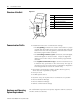
Chapter A Specifications Technical Data Table 1.1 General Specifications Description Specification Standards and regulations EN 61000-6-1; EN 61000-6-2; EN 61000-6-3; EN 61000-6-4, IEC 60068-2-27, IEC 50178 Dimensions W x H x D 35.5 x 90 x 56.5 mm Weight 150 g Mounting DIN 50022 rail, 35 mm screw fixing with fixing bracket ZB4-101-GF1 (accessories) Table 1.
A-2 Specifications Table A.3 Mechanical Ambient Conditions Description Specification Shocks (IEC 60068-2-27) semi-sinusoidal 15 g/11 ms 18 Shocks Drop (IEC 60068-2-31) height 50 mm Free fall, when packed (IEC 60068-2-32) 1m Table A.
Specifications A-3 Table A.6 Tools and Cable Cross-Sections Description Specification Conductor cross-sections Solid, minimum to maximum 0.2 to 4 mm2 , 22 to 12 AWG Conductor cross-sections Flexible with ferrule, minimum to maximum 0.2 to 2.5 mm2 , 22 to 12 AWG Slot-head screwdriver, width 3.5 x 0.8 mm Tightening torque 0.5 Nm Table A.7 Power Supply Description Specification Rated Voltage Value 24V dc Rated Voltage Range 20.4 ... 28.
A-4 Specifications Table A.9 DeviceNet Dimensions Description Specification Bus termination resistors Separate installation at the bus possible Bus addresses, accessible via basic unit with display or Pico-SOFT 0 to 63 Services: Module inputs all data S1 to S8 (Pico Series B) Services: Module outputs all data R1 to R16 (Pico Series B) Services: Module control commands Read/Write Weekday, time-of-day, summer/winter time All parameters of the Pico functions Figure 1.
Glossary Terminating Resistor Terminating resistor at the start and end of a bus cable. Prevents interference due to signal reflection and is used for the adaptation of bus cables. Bus terminating resistors must always be the last unit at the end of a bus segment. Acknowledge Acknowledgement returned by the receiving station after having received a signal. Address Number that identifies a memory area, systems or module within a network, for example.
Glossary 2 Electrical equipment Comprises all equipment used for the generation, conversion, transfer, distribution and application of electrical energy, e.g. power lines, cables, machines, controllers. Reference ground Earth potential in the area of grounding devices. May have a potential other than the zero of "earth" potential. Reference potential Represents a reference point for measuring and/or visualising the voltage of any connected electrical circuits. Bidirectional Operation in both directions.
Glossary 3 Bus cycle time Time interval in which a master provides services to all slaves or nodes of a bus system, i.e. writes data to their outputs and reads inputs. Byte A sequence of 8 bits Code Data transfer format COS I/O connection COS (Change Of State) I/O connections are used to set up event-controlled connections, i.e. the DeviceNet devices automatically generate messages when a status has changed.
Glossary 4 DIN Abbreviation for "Deutsches Institut für Normungen e. V.". Dual Code Natural binary code. Frequently used code for absolute measurement systems. EDS This EDS file primarily defines the Polled I/O Connection, the COS I/O Connection and the Cyclic I/O Connection of the gateway. It does not contain data or parameters (Pico object) for functions of the basic unit. These functions are accessed by means of explicit messages.
Glossary 5 Fieldbus Data network on the sensor/actuator level. The fieldbus interconnects the devices at field level. Characteristic feature of the fieldbus is the highly reliable transfer of signals and real-time response. Field power supply Power supply for the field devices and signal voltage. Galvanic coupling Galvanic coupling generally develops between two circuits using a common cable.
Glossary 6 transformers, motors, mains cables installed parallel and RF signal cables. Capacitive coupling Capacitive (electrical) coupling develops between two conductors carrying different potentials. Typical interference sources are, for example parallel signal cables, contactor relays and static discharge. Coding element Two-part element for the unambiguous allocation of electronic and basic module.
Glossary 7 Master/Slave Mode Operating mode in which a station or node of the system acts as master that controls communication on the bus. Mode Operating mode. Module bus Represents the internal bus of an XI/ON station. Used by the XI/ON modules for communication with the gateway. Independent of the fieldbus. MSB Abbreviation for “Most Significant Bit“. Bit with the most significant value.
Glossary 8 Polled I/O connection A polled I/O connection is used to establish a conventional master/slave relation between a programmable controller and a DeviceNet device, and represents a PtP connection between two stations on the fieldbus. The master (client) transmits a polling request to the slave (server), and this answers with a polling response.
Glossary 9 Shielding Refers to all measures and equipment used to connect system parts to the screen. Protective conductor Conductor required for human body protection against hazardous currents. Abbreviation: PE (“Protective Earth“). Serial Describes an information transfer technique. Data are transferred in a bit-stream across the cables. Slave Station or node in a bus system that is subordinate to the master. Station Function unit or module, consisting of several elements.
Glossary 10 UCMM The DeviceNet gateway provides an option of configuring dynamic connection objects via the UCMM port (Unconnected Message Manager Port). Unidirectional Operating in one direction.
Glossary 11 Notes: Publication 1760-UM003A-EN-P - September 2005
Glossary 12 Publication 1760-UM003A-EN-P - September 2005
Index Numerics 7-day time switch Pico 6-19, 6-32 Pico GFX 7-46 A Address range 3-1 Allen-Bradley contacting for assistance P-3 support P-3 Analog comparators Pico 6-21 Pico GFX 7-22 Pico, read status 6-5 Analog output Pico GFX, read status 7-16 Application Objects 4-4 Application-specific objects 4-4 Arithmetic function block Pico GFX 7-23 Assembly Objects 4-4 Auto baud recognition 2-4 B Bit array 6-3 Block Compare Pico GFX 7-25 Block Transfer Pico GFX 7-27 Boolean operation Pico GFX 7-28 Bus cable length
2 Index High-speed counter Pico GFX 7-33 I Identity Object 4-2 Image data Overview of Pico GFX 7-7 Overview Pico 6-4 Incremental encoder counters Pico GFX 7-35 Initial power on 3-1 Inputs of Pico-LINK Pico GFX, read status 7-18 Pico, read status 6-16 Inputs, network stations Pico GFX, read status 7-11 Invalid operating mode 6-34, 7-64 Invalid telegram 6-34, 7-64 L LED status displays 3-5, 8-1 Local analog output Pico GFX, read status 7-16 Local inputs Pico GFX, read status 7-10 Pico, read status 6-8 Loc
Index Pico GFX 7-45 related publications P-2 Response time of the basic unit 3-6 S SDO Control commands for Pico GFX 7-1 Control commands for Pico Series B 6-1 Send data, network stations read status 7-19 Pico GFX 7-56 Send network data Pico GFX 7-56 Set cycle time Pico GFX 7-60 Setting the address with Pico-SOFT 3-3 Setting the slave address 3-1 Signal smoothing filter Pico GFX 7-43 Structure of the unit 1-2 Summer time Pico GFX 7-4 Switching rule 6-3 Synchronize clock Pico GFX 7-59 System overview 1-1
Rockwell Automation Support Rockwell Automation provides technical information on the web to assist you in using its products. At http://support.rockwellautomation.com, you can find technical manuals, a knowledge base of FAQs, technical and application notes, sample code and links to software service packs, and a MySupport feature that you can customize to make the best use of these tools.