
Software User Manual FRN 1.2 Owner manual

Publication 1758-UM002D-EN-P - October 2010
DataSite DNP3 Configuration Utility (DS DNP3) 249
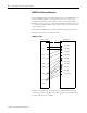
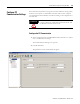
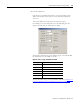
2. Click the Add button.
Each data point is added automatically to the corresponding register
address. The number of data points is an incremental change which
starts at 0.
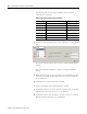
The register addresses correspond to the acquisition signal.
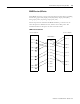
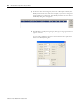
For example, if you click Add, select AI in the Add dialog box that
appears, and click OK, an AI data point is added.
The following table lists the register address ranges of AI, AO, DI, DO,
PI, and String for the 1758-RTU controllers.
To view the address ranges for the 1758-FLO controllers, see Chapter 4
Extension Modbus Protocol for DataSite Controllers (1758-FLO).
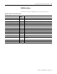
Register address ranges for AI, DO, DI and DO
Signal Type Register Address Range
AI 30001…34096 or 40001…49999
AO 40001…49999
DI 10001…14096 or 1…4096
DO 1…4096
PI 30001…34096 or 40001…49999
String 40003…49999