
Software User Manual FRN 1.2 Owner manual

Publication 1758-UM002D-EN-P - October 2010
DataSite Flow Configuration Utility (DS FloConfig) 219
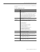
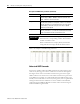
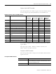
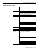
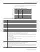
The following tables list the definition of the first two bytes of the response
code according to the HART protocol.
First byte when bit 7 = 1 (Communication Error)
Bit Value Description
6 hex C0 Parity error
5 hex A0 Overrun error
4 hex 90 Framing error
3 hex 88 Checksum error
2 hex 84 0 (reserved)
1 hex 82 Rx buffer overflow
0 hex 81 Overflow (undefined)
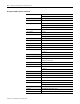
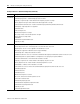
First byte when bit 7 = 0 (Command Response)
Bit Description
0
(1)
No command-specific error
1
(1)
(Undefined)
2
(1)
Invalid selection
3
(1)
Passed parameter too large
4
(1)
Passed parameter too small
5
(1)
Too few data bytes received
6
(1)
Device-specific command error (rarely used)
7 In write-protect mode
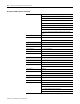
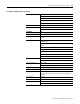
8 This bit can mean any of the following:
•Update failure—Returned real-time data has not changed since last read from field device.
•Warning: Update failure—Real-time data returned has not changed since last read.
•Warning: Set to nearest possible value—Command is accepted but limitations of the field device has caused data sent to
be rounded or truncated.
•Warning: Update in progress—Results of a command are excluded from its status because the command is still in the
process of being completed.
•Warning: External input is not set to 4…20 mA temperature.
•Warning: Time is corrupt.
•Warning: Units and 4/20 points set to new sensor limits.
9 This bit can mean any of the following:
•Lower range value too high—Lower range value is greater than the upper sensor limit.
•Applied process too high—Process applied to the field device is too high.
•Not in proper current mode—Field device is not in fixed current mode, or the current has not been set to the correct value.
•Not in proper analog output mode—Field device is not in fixed analog output mode, or the analog output has not been set
to the correct value.