
Software User Manual FRN 1.2 Owner manual

Publication 1758-UM002D-EN-P - October 2010
DataSite Flow Configuration Utility (DS FloConfig) 141
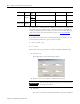
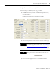
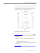
Signal Addresses
You need to enter the addresses for the static pressure (P), temperature (T),
and differential pressure (DP) signals. These are the signals you have
connected using the Analog In (AI) and/or HART channels during the setup
of the DataSite controller. You may choose to use these signals from the
AI0…AI5 channels on the DataSite controller. For more information on the
wiring channel of each field signal, refer to I/O Wiring in the DataSite
Electronic Flow Meter and Remote Terminal Unit Hardware User Manual,
publication 1758-UM001.
Data Type
For each signal address, select its data type.
• UShort: Unsigned short
• Float: Floating point
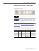
k and b
The linear slope k and constant b are calculated using the engineering
calibration range shown in the following table.
• Hi: the maximum engineering value range of the instrument connected
with the AI channel.
• Lo: the minimum engineering value range of the instrument connected
with the AI channel.
These are the default ranges for each signal.
• DP: 0…150 in H
2
O of 60 ºF
• P: 0…1500 psia
• T: 0…150 ºF
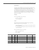
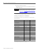
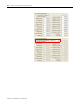
Input Address Data
Type
Data k b
AI0 30001 USHORT 1000…50000 Sampled processed value (Hi-Lo)/(50000-10000) Lo-10000*k
AI1 30002 USHORT 1000…50000 Sampled processed value (Hi-Lo)/(50000-10000) Lo-10000*k
AI2 30003 USHORT 1000…50000 Sampled processed value (Hi-Lo)/(50000-10000) Lo-10000*k
AI3 30004 USHORT 1000…50000 Sampled processed value (Hi-Lo)/(50000-10000) Lo-10000*k
AI4 30005 USHORT 1000…50000 Sampled processed value (Hi-Lo)/(50000-10000) Lo-10000*k
AI5 30006 USHORT 1000…50000 Sampled processed value (Hi-Lo)/(50000-10000) Lo-10000*k