Installation Instructions DataSite Natural Gas Flow Meter and Remote Terminal Unit Catalog Numbers 1758-FLO301, 1758-FLO302, 1758-RTU201, 1758-RTU202 Topic Page Important User Information 2 Environment and Enclosure 3 Hazardous Location Considerations 3 Overview 4 Controller Description 5 Mounting the Controller 6 DIN Rail Mounting 7 Power Source Requirements 9 Wiring for Power Supply Input 9 Wire the Controller for HART Communication 14 Ground the Module 15 Status Indicators 20 S
DataSite Natural Gas Flow Meter and Remote Terminal Unit Important User Information Solid state equipment has operational characteristics differing from those of electromechanical equipment. Safety Guidelines for the Application, Installation and Maintenance of Solid State Controls (Publication SGI-1.1 available from your local Rockwell Automation sales office or online at http://literature.rockwellautomation.
DataSite Natural Gas Flow Meter and Remote Terminal Unit 3 Environment and Enclosure ATTENTION Do not remove the protective debris strip until after the module and all other equipment in the panel near the module are mounted and wiring is complete. Once wiring is complete, remove protective debris strip. Failure to remove strip before operating can cause overheating. ATTENTION Electrostatic discharge can damage semiconductor devices inside the module.
DataSite Natural Gas Flow Meter and Remote Terminal Unit Environnements dangereux Cet équipement est conçu pour une utilisation en environnements dangereux de Classe I, Division 2, Groupes A, B, C, D. La mise en garde suivante s’applique à utilisation en environnements dangereux. WARNING DANGER D’EXPLOSION • La substitution de composants peut rendre cet équipement impropre à une utilisation en environnement de Classe I, Division 2.
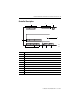
DataSite Natural Gas Flow Meter and Remote Terminal Unit 5 Controller Description 1 DICOM DI0 DI1 DI2 DI3 DI4 DI5 DI6 DI7 2 3 + _ WAKEUP ON 9 10 0 1 2 H0+ H0- H1+ H1- H2+ H2- P10 P11 P12 PI AOV+ AOV- AO0 AOV- AO1 AOVCOM Data V+ V- AI0 AI1 AI2 AI3 AI4 AI5 V- DO0 DO1 DO2 DO3 VDO+ VDO- + _ 44376 44379 8 7 Item Description 1 Discrete Inputs and wake up connectors 2 Status indicators 3 Ethernet connector 4 RS 232 COM 2 connector 5 RS 232 COM 1 connector 6 RS 485 COM 1 connector 7
DataSite Natural Gas Flow Meter and Remote Terminal Unit Mounting the Controller Most applications require installation in an industrial enclosure to reduce the effects of electrical interference and environmental exposure. Locate your controller as far as possible from power lines, load lines, and other sources of electrical noise such as hard-contact switches, relays, and AC motor drives.
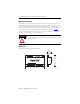
DataSite Natural Gas Flow Meter and Remote Terminal Unit 7 Controller Spacing When mounting the controller, allow 25 mm (1 in.) of space on all sides for adequate ventilation, as shown below. Top Side Side Bottom 44375 DIN Rail Mounting A small Phillips screwdriver is required for the installation or removal of the controller. The controller can be mounted to EN50022-35 x 7.5 DIN rails. Follow these steps to install your controller on the DIN rail. 1. Mount your DIN rail.
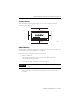
DataSite Natural Gas Flow Meter and Remote Terminal Unit 4. Slide the clamp out while pushing the controller fully onto the DIN rail (1). When the controller is properly aligned on the DIN rail (2), slide the clamp in, so that it makes direct contact with the lower edge of the DIN rail (3). 1 2 3 DIN rail 44538 44539 44540 5. Tighten the clamp screws. Follow these steps to remove your controller from the DIN rail. 1.
DataSite Natural Gas Flow Meter and Remote Terminal Unit 9 Power Source Requirements The DataSite modules (1758-FLO301, 1758-FLO302, 1758-RTU201, 1758-RTU202) must be powered by a National Electrical Code (NEC) or Canadian Electrical Code (CEC) Class 2 power source when used in locations covered by Underwriters Laboratories. In locations governed by International Electrotechnical Commission (IEC) or EN standards, a Safety Extra Low Voltage (SELV) power source must be used.
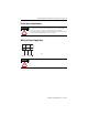
DataSite Natural Gas Flow Meter and Remote Terminal Unit Wire the Controller for Analog Input The analog input circuits are equipped with overvoltage and overcurrent protection. 4 5 6 7 8 9 AI0 AI1 AI2 AI3 AI4 AI5 Two wire sensor 10 V- Three wire sensor 44381 24VDC WARNING Power Supply Refer to Power Source Requirements for details on wiring.
DataSite Natural Gas Flow Meter and Remote Terminal Unit 11 Wire the Controller for Digital Input 19 20 21 22 23 24 25 26 27 DICOM DI0 DI1 DI2 DI3 DI4 DI5 DI6 DI7 28 44383 12~24V DC WARNING Refer to Power Source Requirements for details on wiring. Wire the Controller for Digital Output 13 14 D00 D01 D02 D03 D0V+ D0V- LOAD LOAD 15 16 LOAD 12 LOAD 24V FET OUTPUT 11 12~24V WARNING 44384 Refer to Power Source Requirements for details on wiring.
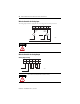
DataSite Natural Gas Flow Meter and Remote Terminal Unit Wire the Controller for Pulse Input 35 36 37 38 39 PI0 PI1 PI2 PI- 40 44385 12~24V Refer to Power Source Requirements for details on wiring.
DataSite Natural Gas Flow Meter and Remote Terminal Unit 13 RS232 DTE to RS232 DTE with Handshaking RS232 (DTE) DCD 1 RXD 2 TXD 3 DTR 4 GND 5 6 RTS 7 CTS 8 9 DTE 1 2 3 4 5 6 7 8 9 DCD RXD TXD DTR GND RTS CTS 44388 RS232 DTE to RS232 DCE with Handshaking RS232 (DTE) DCE DCD RXD TXD DTR GND 1 2 3 4 5 6 7 8 9 RTS CTS 1 2 3 4 5 6 7 8 DCD RXD TXD DTR GND RTS CTS 44389 Publication 1758-IN001C-EN-P - June 2011
DataSite Natural Gas Flow Meter and Remote Terminal Unit Wiring for RS485 Serial Communications Master Station First station in network requires terminations D D Slave Station D D RS-485 network 1200 m (4000 feet) maximum length Slave Station D D Last station in network requires terminations 44390 Wire the Controller for HART Communication The controller comes with three HART protocol communications ports, including one that is multi-point, and can connect to thirteen HART protocol meters.
DataSite Natural Gas Flow Meter and Remote Terminal Unit 15 HART1 or HART2 point-to-point wiring to passive meters H1+ H1- H2+ Two Wire Slave #1 H2- Two Wire Slave #2 DC Power Supply DC Power Supply 44393 Wire the Controller for Sleep/Wake Up mode To reduce power consumption in unattended or solar-powered applications, the controller can be configured to enable Sleep mode, and disable Sleep mode when inputs are detected.
DataSite Natural Gas Flow Meter and Remote Terminal Unit You must also provide an acceptable grounding path for each device in your application. For more information on proper grounding guidelines, refer to the Industrial Automation Wiring and Grounding Guidelines, publication 1770-4.1. Battery Status Check The DataSite controller uses a lithium battery that allows the real-time-clock (RTC) to maintain the correct time setting through periods when line power has been removed from the unit.
DataSite Natural Gas Flow Meter and Remote Terminal Unit 17 Decommission and Recycle the Battery WARNING IMPORTANT WARNING The lithium battery is not user replaceable. Follow the instructions in this section to remove the battery from the DataSite unit for recycling when decommissioning the DataSite unit. Dispose of used battery promptly. Keep away from children. Do not disassemble and do not dispose of in fire.
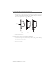
DataSite Natural Gas Flow Meter and Remote Terminal Unit 2. Pry the board off from the standoffs. 44738 3. Use a flat-blade screwdriver to pry the battery out from under the clamp.
DataSite Natural Gas Flow Meter and Remote Terminal Unit 19 4. Remove the battery. CR2325 LITHIUM BATTERY 44740 5. Replace the board onto the standoffs. 44741 6. Replace the cover, and fasten the screws securely.
DataSite Natural Gas Flow Meter and Remote Terminal Unit Status Indicators PWR STAT DO0 DO2 RUN ERR DI0 DI2 DI4 DI6 PI0 PI2 TX0 TX1 DO1 DO3 DI1 DI3 DI5 DI7 PI1 LINK RX0 RX1 TX2 10\100M RX2 F\H Indicator State Description PWR Green Power is applied. This indicator is not affected by LED power control settings. RUN Green Normal operation. This indicator is not affected by LED power control settings.
DataSite Natural Gas Flow Meter and Remote Terminal Unit 21 Specifications General Attribute Description Dimensions 213 x 133 x 56 mm (8.375 x 5.25 x 2.20 in.) Number of I/O 8 digital inputs 4 digital outputs 8 analog inputs 2 analog outputs 3 pulse inputs Power supply voltage 12V DC, (-15%, +10%) Heat dissipation, nominal < 1.2 W Power consumption 80…120 mA Input circuit type Current Sinking Output circuit type Current Sourcing (FET) Terminal screw torque 0.
DataSite Natural Gas Flow Meter and Remote Terminal Unit Digital Input Attribute Description On-state voltage range 8…24V DC Off-state voltage range 0…4V DC Operating frequency 100 Hz On-state current, min 3 mA On-state current, nom 5 mA On-state current, max 11 mA Off-state leakage current 2 mA Nominal impedance 2.
DataSite Natural Gas Flow Meter and Remote Terminal Unit 23 Analog Inputs Attribute Description Voltage input impedance 100 kΩ for 10V DC inputs 170 Ω for 20 mA inputs Input Resolution 16-bit Non-linearity ±0.1% of full scale Overall accuracy ±0.1% of full scale at 25 °C ±0.
DataSite Natural Gas Flow Meter and Remote Terminal Unit HART Attribute Description Output impedance 300 Ω transformer isolated Input impedance 4000 Ω transformer isolated Load resistor 250 Ω, 1 W max Environmental Specifications Attribute Value Temperature, operating -40... 70 °C (-40 ...158 °F) Temperature, non-operating -50...80 °C (-58... 176 °F) Relative humidity 5...95% non-condensing Vibration IEC 60068-2-6 Constant amplitude 0.
DataSite Natural Gas Flow Meter and Remote Terminal Unit 25 Environmental Specifications Attribute Value EFT/B immunity IEC 61000-4-4: ±2 kV at 5 kHz on power ports ±2 kV at 5 kHz on signal ports ±1 kV at 5 kHz on communications ports Surge transient immunity IEC 61000-4-5: ±1 kV line-line(DM) and ±2 kV line-earth(CM) on power ports ±1 kV line-line(DM) and ±2 kV line-earth(CM) on signal ports ±1 kV line-earth(CM) on shielded ports ±1 kV line-earth(CM) on communications ports Conducted RF immunity I
DataSite Natural Gas Flow Meter and Remote Terminal Unit Additional Resources These documents contain additional information concerning related Rockwell Automation products. Resource Description DataSite Electronic Flow Meter and Remote Terminal Unit Hardware User Manual 1758-UM001 Information on how to install and wire a DataSite controller.
DataSite Natural Gas Flow Meter and Remote Terminal Unit 27 Notes: Publication 1758-IN001C-EN-P - June 2011
Rockwell Automation Support Rockwell Automation provides technical information on the Web to assist you in using its products. At http://support.rockwellautomation.com, you can find technical manuals, a knowledge base of FAQs, technical and application notes, sample code and links to software service packs, and a MySupport feature that you can customize to make the best use of these tools.