
Hardware User Manual Manual


Publication 1758-UM001D-EN-P - June 2011
48 Operating the Controller
Sleep Mode
Sleep mode is available on 1758-RTU controllers only. 1758-FLO controllers
do not provide Sleep mode due to requirements for periodic execution of the
AGA gas flow calculations.
DataSite controllers are capable of extremely low power operation when in
Sleep mode. In Sleep mode, the following will occur:
• All programs stop executing.
• The power supply of 3.3V for circuit is shut off.
• The real-time clock and timer continue to function.
• 12V DC power is not affected.
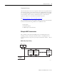
DataSite controllers can switch to Sleep mode under control of the application
program. If one of the following conditions occurs, the controller will be
switched out of Sleep mode to return to normal operation.
• A real-time clock alarm, as defined by an application program, is
triggered.
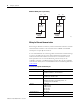
• A high voltage level signal is applied to the WakeUp input.
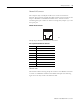
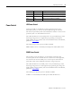
LED Indicators
Indicator State Description
PWR Green Power is applied. This indicator is not affected by
LED power control settings.
RUN Green Normal operation. This indicator is not affected by
LED power control settings.
STAT Flasing red DataSite application running
ERR Yellow Error detected
DI0…DI7 Green Corresponding digital input is on
DO0…DO3 Green Corresponding digital output is on
PI0…PI2 Green Corresponding pulse input voltage is more than 8V
TX0 Flashing red Transmitting data through HART port
RX0 Flashing green Receiving data through HART port
TX1 Flashing red Transmitting data through serial port 1
RX1 Flashing green Receiving data through serial port 1
TX2 Flashing red Transmitting data through serial port 2
PWR STAT DO0 DO2 DI0 DI2 DI4 DI6 PI0 PI2 TX0 TX1 TX2 10\100M
RUN ERR DO1 DO3 DI1 DI3 DI5 DI7 PI1 LINK RX0 RX1 RX2 F\H