
Hardware User Manual Manual

Publication 1758-UM001D-EN-P - June 2011
Wiring the Controller 35
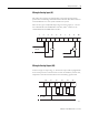
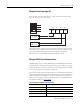
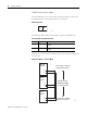
Wiring for Pulse Count Input (PI)
Counter inputs operate as DC inputs or as high-speed counter inputs. This
figure shows how to wire these inputs.
Each pulse input has a filter circuit that allows more reliable operation in noisy
environments, but at reduced counting frequency. The factory default setting
of the filter is disabled, allowing operation to 10 KHz. With the filter
DIP-switch set to on, maximum frequency is reduced to 30 Hz.
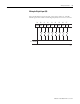
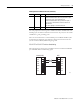
Wiring for RS232 Serial Communications
Shielded cabling must be used for RS232 wiring in the DataSite controller. The
shield should be connected to chassis ground at one point. Failure to properly
shield the cable may result in the installation not complying with FCC or DOC
wireless electromagnetism interference regulations.
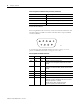
The following table shows the serial and protocol communication parameters
supported by RS232 Serial port. These parameters are set from the DS Setting
software utility for the 1758-RTU controller or the DS FloConfig software
utility for the 1758-FLO controller. For details, refer to the DataSite Software
User Manual, publication 1758-UM002
.
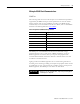
Serial and protocol communication parameters
Parameter Engineering value
Baud rate (bps) 2400, 4800, 9600, 19200, 38400, 57600
Communication duplex mode Full Duplex, Half Duplex
Parity Odd, None or Even
Data bits 7 or 8 bits
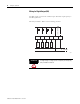
PULSE OUTPUT
DEVICE (12…24 V)
12…24 V
ON
Filter PI0
Filter PI1
Filter PI2
PI0 PI1 PI2 PI-COM
3736 38
39
44695