
Hardware User Manual Manual

23 Publication 1758-UM001D-EN-P - June 2011
Chapter
3
Wiring the Controller
This chapter describes how to wire the DataSite controller.
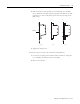
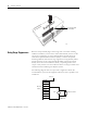
Connectors on the DataSite
Controller
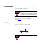
The connecting terminal of the DataSite controller can be divided into three
parts:
• Power supply input terminal
• I/O signal wire connecting terminal, such as AI, DI, DO, AO, PI,
Wake up, and HART.
• Local/long-distance communication terminal, such as COM1
(RS232/RS485), COM2 (RS232), and the Ethernet interface.
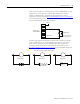
The distribution of terminal groups is shown as follows:
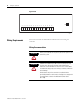
Lower Board
DICOM
DI0
V+ V- AI0 AI1 AI2 AI3 AI4 AI5 V- DO0 DO1 DO2 DO3 V
DO+
V
DO-
DI1 DI2 DI3 DI4 DI5 DI6 DI7
WAKEUP
+
_
Data
+
_
P1 P2
P3
P4 P5
P6
P7
23456789101111213141516
19
20 21 22 23 24 25 26 27 28 29
17 18
44624