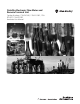
DataSite Electronic Flow Meter and Remote Terminal Unit Catalog Numbers 1758-FLO301, 1758-FLO302, 1758RTU201, 1758-RTU202 Hardware User Manual
Important User Information Solid state equipment has operational characteristics differing from those of electromechanical equipment. Safety Guidelines for the Application, Installation and Maintenance of Solid State Controls (publication SGI-1.1 available from your local Rockwell Automation sales office or online at http://literature.rockwellautomation.com) describes some important differences between solid state equipment and hard-wired electromechanical devices.
Table of Contents Table of Contents Preface Who Should Use this Manual . . . . . . . . . . . . . . . . . . . . . . . . . . . . . . . . . 5 Purpose of this Manual . . . . . . . . . . . . . . . . . . . . . . . . . . . . . . . . . . . . . . 5 Related Documentation . . . . . . . . . . . . . . . . . . . . . . . . . . . . . . . . . . . . . . 5 Common Techniques Used in this Manual. . . . . . . . . . . . . . . . . . . . . . . 6 Chapter 1 Overview Introduction . . . . . . . . . . . . . . . . . . . . . . . . . .
Table of Contents Power Wiring . . . . . . . . . . . . . . . . . . . . . . . . . . . . . . . . . . . . . . . . . . . . . 29 I/O Wiring . . . . . . . . . . . . . . . . . . . . . . . . . . . . . . . . . . . . . . . . . . . . . . . 30 Minimizing Electrical Noise . . . . . . . . . . . . . . . . . . . . . . . . . . . . . . 30 Wiring for Analog Input (AI) . . . . . . . . . . . . . . . . . . . . . . . . . . . . . 31 Wiring for Analog Output (AO) . . . . . . . . . . . . . . . . . . . . . . . . . . .
Preface Read this preface to familiarize yourself with the rest of the manual. It provides information concerning: • • • • Who Should Use this Manual who should use this manual the purpose of this manual related documentation conventions used in this manual Use this manual if you are responsible for designing, installing, programming, or troubleshooting control systems that use DataSite controllers. You should have a basic understanding of electrical circuitry and familiarity with relay logic.
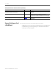
Preface Related publications for DataSite controllers (Continued) Pub. Title Pub. Number Description National Electrical Code - Published by the National Fire Protection Association of Boston, MA. — An article on wire sizes and types for grounding electrical equipment. Allen-Bradley Publication Index SD499 — A complete listing of current documentation, including ordering instructions. Also indicates whether the documents are available on CD-ROM or in multi-languages.
Chapter 1 Overview Introduction The Allen-Bradley DataSite controller is an excellent remote terminal unit for service in harsh and extreme industrial environments such as oil, gas, pipeline, and electrical utility applications. It is ideal for applications that require wide temperature ratings and low power consumption, and applications that are remote and powered by solar cells or wind power. The DataSite controller has a high-performance 32-bit ARM processor with several communications options.
Overview 1758-FLO DataSite controllers In addition to the features listed in preceding sections, the 1758-FLO DataSite controllers provide the additional feature of being able to calculate gas flow.
Overview 9 • Working temperature of -40…70 °C, humidity: 5…95% RH, which is applicable for a range of different environments. Controller Description The components of the DataSite controller are shown here.
Overview Notes: Publication 1758-UM001D-EN-P - June 2011
Chapter 2 Installing the Controller This chapter shows you how to install the DataSite controller. The only tool you require is a Phillips head screwdriver.
Installing the Controller Locate your controller as far as possible from power lines, load lines, and other sources of electrical noise such as hard-contact switches, relays, and AC motor drives. For more information on proper grounding guidelines, see the Industrial Automation Wiring and Grounding Guidelines, publication 1770-4.1. Safety Considerations ATTENTION Electrostatic discharge can damage semiconductor devices inside the controller. Do not touch the connector pins or other sensitive areas.
Installing the Controller 13 Use only the following communication cables in Class I, Division 2 hazardous locations. Communication Cables for Class I, Division 2 Hazardous Locations Description Catalog No. This 3.96 m (12 ft) cable has two 9-pin DTE connectors and is used to connect the RS232 channel (Channel 1 or 2) on the DataSite controller to a serial port on a personal computer.
Installing the Controller Disconnecting Main Power WARNING Explosion Hazard Do not replace components, connect equipment, or disconnect equipment unless power has been switched off. The main power disconnect switch should be located where operators and maintenance personnel have quick and easy access to it. In addition to disconnecting electrical power, all other sources of power (pneumatic and hydraulic) should be de-energized before working on a machine or process controlled by a controller.
Installing the Controller 15 Power Distribution There are some points about power distribution that you should know: • The master control relay must be able to inhibit all machine motion by removing power to the machine I/O devices when the relay is de-energized. It is recommended that the controller remain powered even when the master control relay is de-energized. • If you are using a DC power supply, interrupt the load side rather than the AC line power.
Installing the Controller Input States on Power Down The power supply hold-up time as described above is generally longer than the turn-on and turn-off times of the inputs. Because of this, the input state change from On to Off that occurs when power is removed may be recorded by the processor before the power supply shuts down the system. Understanding this concept is important. The user program should be written to take this effect into account.
Installing the Controller Master Control Relay 17 A hard-wired master control relay (MCR) provides a reliable means for emergency machine shutdown. Since the master control relay allows the placement of several emergency-stop switches in different locations, its installation is important from a safety standpoint. Overtravel limit switches or mushroom-head push buttons are wired in series so that when any of them opens, the master control relay is de-energized.
Installing the Controller Using Emergency-Stop Switches When using emergency-stop switches, adhere to the following points: • Do not program emergency-stop switches in the controller program. Any emergency-stop switch should turn off all machine power by turning off the master control relay. • Observe all applicable local codes concerning the placement and labeling of emergency-stop switches. • Install emergency-stop switches and the master control relay in your system.
Installing the Controller Controller Mounting Dimensions 19 The dimensions of the DataSite controller are shown in this diagram. The dimensions are identical for all DataSite catalog numbers. 1758-FLO301, 1758-FLO302, 1758-RTU201, 1758-RTU202 Front view Side view 5.6 cm (2.20 in) 13.0 cm (5.12 in) 21.3 cm (8.395 in) Controller Spacing 44374 When mounting the controller, allow 25 mm (1 in.) of space on all sides for adequate ventilation.
Installing the Controller Mounting the Controller DataSite controllers are suitable for use in an industrial environment when installed in accordance with these instructions. Specifically, this equipment is intended for use in clean, dry environments (Pollution degree 2(1)) and to circuits not exceeding Over Voltage Category II(2) (IEC 60664-1).(3) ATTENTION Electrostatic discharge can damage semiconductor devices inside the controller. Do not touch the connector pins or other sensitive areas.
Installing the Controller 21 4. Slide the clamp out while pushing the controller fully onto the DIN rail (1). When the controller is properly aligned on the DIN rail (2), slide the clamp in, so that it make direct contact with the lower edge of the DIN rail (3). 1 2 3 DIN rail 44538 44539 44540 5. Tighten the clamp screws. Follow these steps to remove your controller from the DIN rail. 1.
Installing the Controller Notes: Publication 1758-UM001D-EN-P - June 2011
Chapter 3 Wiring the Controller This chapter describes how to wire the DataSite controller. Connectors on the DataSite Controller The connecting terminal of the DataSite controller can be divided into three parts: • Power supply input terminal • I/O signal wire connecting terminal, such as AI, DI, DO, AO, PI, Wake up, and HART. • Local/long-distance communication terminal, such as COM1 (RS232/RS485), COM2 (RS232), and the Ethernet interface.
Wiring the Controller Upper Board ON 30 31 32 33 34 35 36 37 38 39 40 41 42 43 44 0 1 2 45 H0+ H0- H1+ H1- H2+ H2- P10 P11 P12 PI AOV+ AOV- AO0 AOV- AO1 AOVCOM P7 44625 Wiring Requirements This section contains recommendations and instructions for wiring the controller. Wiring Recommendation ATTENTION Before you install and wire any device, disconnect power to the controller system. ATTENTION Calculate the maximum possible current in each power and common wire.
Wiring the Controller 25 • Allow for at least 50 mm. (2 in.) between I/O wiring ducts or terminal strips and the controller. • Route incoming power to the controller by a path separate from the device wiring. Where paths must cross, their intersection should be perpendicular. Do not run signal or communications wiring and power wiring in the same conduit. Wires with different signal characteristics should be routed by separate paths. TIP • Separate wiring by signal type.
Wiring the Controller 30 35 34 33 32 31 36 37 38 39 40 41 42 43 44 Screw-cage clamp terminal block 45 17 15 14 11 12 18 16 13 10 9 8 7 6 5 4 3 2 1 44756 Using Surge Suppressors Because of the potentially high current surges that occur when switching inductive load devices, such as motor starters and solenoids, the use of some type of surge suppression to protect and extend the operating life of the controllers output field effect transistors (FETs) or contacts is required
Wiring the Controller 27 If the outputs are DC, we recommend that you use an 1N4004 diode for surge suppression, as shown below. For inductive DC load devices, a diode is suitable. A 1N4004 diode is acceptable for most applications. A surge suppressor can also be used. See Recommended Surge Suppressors on page 28 for recommended suppressors. As shown below, these surge suppression circuits connect directly across the load device.
Wiring the Controller Recommended Surge Suppressors Use the Allen-Bradley surge suppressors shown in the following table for use with relays, contactors, and starters.
Wiring the Controller Grounding the Controller 29 In solid-state control systems, grounding and wire routing helps limit the effects of noise due to electromagnetic interference (EMI). Run the ground connection from the ground terminal of the controller to the ground bus prior to connecting any devices. Use AWG #14 wire. ATTENTION All devices connected to the RS232/RS485 communication port must be referenced to controller ground, or be floating (not referenced to a potential other than ground).
Wiring the Controller I/O Wiring For the orifice plate metering (AGA3), the input signals are differential pressure, static pressure, and temperature. For the turbine metering (AGA7), the input signals are pulse counting, static pressure, and temperature. The Datasite controller has 8-analog input channels (two channels also provide a HART point-to-point interface), a 13 device HART multi-point interface, and 3-channel pulse counting (PI) acquisition channels.
Wiring the Controller Wiring for Analog Input (AI) The analog input circuits are equipped with overvoltage and overcurrent protection to avoid damage due to false field connection. The field connection can be divided into two-wire system and three-wire system. There are two types of adjustable input ranges for analog inputs, 0…10V for the 1758-FLO301 and 1758-RTU201 controllers, and 4…20 mA for the 1758-FLO302 and 1758-RTU202 controllers.
Wiring the Controller Minimizing Electrical Noise on Analog Channels Inputs on analog channels employ digital high-frequency filters that significantly reduce the effects of electrical noise on input signals. However, because of the variety of applications and environments where analog controllers are installed and operated, it is impossible to ensure that all environmental noise is removed by the input filters.
Wiring the Controller Wiring for Digital Input (DI) Keep the DI effective high level input voltage range within 12…24V DC. The DI signal can be used to measure digital quantity such as the on/off state.
Wiring the Controller Wiring for Digital Output (DO) The DO output is in the form of FET outputs. The FET output capacity is 24V DC @ 200 mA. DO arrays are DO0…DO3 on the connecting terminal. POWER SUPPLY DO0 11 DO1 12 DO2 13 DO3 14 DOV+ 15 DOV- 16 LOAD LOAD LOAD LOAD 12…24 V DC 44694 ATTENTION Publication 1758-UM001D-EN-P - June 2011 If a high voltage or a large current is required, an interposing relay should be connected.
Wiring the Controller 35 Wiring for Pulse Count Input (PI) Counter inputs operate as DC inputs or as high-speed counter inputs. This figure shows how to wire these inputs. Filter PI0 Filter PI1 36 37 38 39 PI0 PI1 PI2 PI-COM Filter PI2 ON 12…24 V PULSE OUTPUT DEVICE (12…24 V) 44695 Each pulse input has a filter circuit that allows more reliable operation in noisy environments, but at reduced counting frequency.
Wiring the Controller Serial and protocol communication parameters (Continued) Parameter Engineering value Stop bits 1 or 2 bits Communication protocol Modbus RTU, Modbus ASCII, DNP3 Protocol mode Master, Slave (DNP3 supports only slave mode.) Connecting type DB-9P RS232 DB-9P Connector When using RS232 serial connection, connect the interface COM of PC and interface COM1 or COM2 of controller with data cables of 9-pin standard connector (DB-9P).
Wiring the Controller 37 Pin Assignments for RS232 Connector (Continued) Pin Function Type Description Pin 8 CTS Input EFFECTIVE for the communication port to transmit data. When the attached device does not provide this signal, the controller stays at an EFFECTIVE level. When the attached device does provide this signal, it must set CTS to EFFECTIVE to allow the controller to transmit data. CTS LED is lighting for an EFFECTIVE level. Pin 9 — NC This pin is not connected.
Wiring the Controller RS232 DTE to RS232 DTE with Handshaking Some DTE (Data Terminal Equipment) require handshaking signal wires. For details, refer to the relevant DTE manuals. The wires CTS, RTS, DTR and DCD are used rarely. The following figure shows a standard connection mode between RS232 port and DTE with handshaking signal.
Wiring the Controller 39 Wiring for RS485 Serial Communications RS485 Port The following table shows the serial and protocol communication parameters supported by the RS485 serial port. These parameters are set from the DS Setting software utility for the 1758-RTU controller or the DS FloConfig software utility for the 1758-FLO controller.. For details, refer to the DataSite Software User Manual, publication 1758-UM002.
Wiring the Controller RS485 Two-wire Connection Mode When the RS485 port uses a 2-bit fixed connecting terminal to connect with the RS485 network, it runs primarily in the two-wire mode. RS485 Termination 17 18 Data+ Data- 44699 The following table describes each termination signal of the RS485 port. Pin Assignments for RS485 Connector Pin Function Description 17 Data+ The terminal is the differential input/output positive terminal.
Wiring the Controller Termination Resistors 120-ohm termination resistors are required on each of the two physical ends of one network segment. It also means that the two communication ports which are on the physical end position of one network segment must be connected with termination resistors. Other communication ports of this network segment should not be connected with termination resistors. See RS485 Field Wiring—Two-wire Mode on page 40.
Wiring the Controller HART1 or HART2 point-to-point wiring 32 33 34 35 H1+ H1- H2+ H2- Two Wire Slave #1 DC Power Supply Two Wire Slave #2 DC Power Supply 44703 Wiring for Ethernet Communication When using an Ethernet connection, connect the Ethernet interface of the PC and the Ethernet interface of the controller with a 10BASE-T unshielded twisted pair of a 8-pin RJ-45 connector. It is recommended that the connecting cable of the Ethernet interface belongs to category 5E cable.
Wiring the Controller 43 Ethernet RJ-45 connector The receptacle (P8) of the RJ-45 module is the connection terminal of Ethernet. The receptacle of the RJ-45 module matches its 8-pin connector and adopts a 10BASE-T Unshielded Twisted Pair. Pins 1 and 2 are used for transmitting data, pins 3 and 6 are used for receiving data, and pins 4, 5, 7 and 8 are spare pins.
Wiring the Controller Ethernet to PC Ethernet RJ-45 PC RJ-45 TD+ 1 1 TD+ TD- 2 2 TD- RD+ 3 3 RD+ NC 4 4 NC NC 5 5 NC RD- 6 6 RD- NC 7 7 NC NC 8 8 NC 44628 The Ethernet cable connecting the RJ-45 connector of the DataSite controller to the Ethernet Switch is a 10BASE-T standard non-shielded twisted pair. The following figure shows the array mode of the Ethernet cable.
Wiring the Controller 45 Wiring for Wake Up mode IMPORTANT Wake Up mode is applicable to only 1758-RTU controllers. To reduce power consumption in unattended or solar-powered applications, the controller can be configured to enable Sleep mode by programming the PW_SHDN function block. To exit Sleep mode and wake up the controller, input a high voltage level to the WAKEUP terminal.
Wiring the Controller Notes: Publication 1758-UM001D-EN-P - June 2011
Chapter 4 Operating the Controller This chapter describes the modes of operation for the DataSite controller. Operating Modes You may start up the DataSite controller in the Run or the Service mode. Starting the controller in the Run mode automatically executes DataSite Workbench programs in the controller memory. Starting the controller in the Service mode allows the controller to be initialized. Run Mode Run mode is the normal or default operating mode of the DataSite controller.
Operating the Controller Sleep Mode Sleep mode is available on 1758-RTU controllers only. 1758-FLO controllers do not provide Sleep mode due to requirements for periodic execution of the AGA gas flow calculations. DataSite controllers are capable of extremely low power operation when in Sleep mode. In Sleep mode, the following will occur: • • • • All programs stop executing. The power supply of 3.3V for circuit is shut off. The real-time clock and timer continue to function.
Operating the Controller Power Control Indicator State Description RX2 Flashing green Receiving data through serial port 2 LINK Flashing yellow Transmitting or receiving data through Ethernet port 10\100M Red speed for ethernet connection, 10Mpbs or 100Mpbs F\H Green Ethernet mode, half duplex or full duplex 49 LED Power Control Lighting the LEDs on the DataSite controller board consumes power. To conserve power, you can turn off these LEDs through the controller.
Operating the Controller Ethernet Power Control The Ethernet port on the DataSite controller board consumes power. If the controller does not connect with an equipment through Ethernet port, controller can shut the Ethernet port to conserve power. This feature is particularly useful when the DataSite controller is using solar power. The enable/disable status of Ethernet port power is set by the DS Settings or DS FloConfig configuration tool.
Operating the Controller Real-Time Clock 51 The real-time clock of the DataSite controller provides the time and date independently for the operating system. The time and date remain correct during power off. The calendar automatically manages leap years. Real time clock can be saved into register by reading through the DataSite function block, [CLOCK_GET]. The values for the data and time date are stored in single registers as two-digit values.
Operating the Controller Assigned Modbus Register Addresses of I/O Signals The I/O points of the controller are: 6AI-3HART-8DI-4DO-2AO-3PI-1RS232-1RS232/1RS485-1Ethernet-12VDC When we read or write those signals, we only need to read or write the registers as shown in the following table. Signal Registers Value range Meaning 6AI 30001…30006 10000…50000 Unsigned short data, standard value, readable only. 2HART (2AI) 30007…30008 10000…50000 Unsigned short data, standard value, readable only.
Operating the Controller 53 For 2AO (4…20 mA): Scan Settings of Equipment Connected with COMs Standard value Current 10000 4.00 mA 20000 8.00 mA 30000 12.00 mA 40000 16.00 mA 50000 20.00 mA There are 1RS232/1RS485-1RS232 serial communications on the DataSite controller. The CPU of the controller neeeds to be configured in order to read and write data from equipment connected with the two COMs.
Operating the Controller Lithium Battery The DataSite controller uses a lithium battery that allows the real-time-clock (RTC) to maintain the correct time setting through periods when line power has been removed from the unit. Current drain on the battery during these periods is approximately 1 microamp. The battery should provide approximately 5 years of operation for the RTC. The battery is also rated to maintain the real-time clock and RAM data for two years continuously without any external power.
Operating the Controller 55 If the battery voltage should drop below 2.0 V, contact your Rockwell Automation Support or your local Rockwell Automation representative to arrange for a repair or exchange of the DataSite controller. Decommission and Recycle the Battery ATTENTION The lithium battery is not user replaceable. Follow the instructions in this section to remove the battery from the DataSite unit for recycling when decommissioning the DataSite unit.
Operating the Controller Follow these steps to remove the battery. 1. Remove the cover by first removing the screws on either side of the controller. 44737 2. Pry the board off from the standoffs.
Operating the Controller 57 3. Use a flat-blade screwdriver to pry the battery out from under the clamp. CR2032 LITHIUM BATTERY 44739 4. Remove the battery.
Operating the Controller 5. Replace the board onto the standoffs. 44741 6. Replace the cover, and fasten the screws securely.
Appendix A Specifications This appendix provides the following information: • Controller Specifications • Flow Measurement Parameters Controller Specifications General 59 Attribute Value Dimensions 213 x 133 x 56 mm 8.375 x 5.25 x 2.20 in. Number of I/Os 8 digital inputs 4 digital outputs 8 analog inputs 2 analog outputs 3 pulse inputs Power supply voltage 12V DC, (-15%, +10%) Power consumption 80…120 mA Heat dissipation, nom. < 1.
Specifications CPU Attribute Value Processor 32-bit ARM processor 30 MHz clock frequency Integrated watchdog timer Memory 2 M (program Flash) 4 M (data Flash) 1 M (data SRAM) 32 K FRAM Non-volatile RAM With no power, the Flash storage with lithium battery retains data for five years.
Specifications 61 Digital Output Attribute Value Power supply 12V…24V DC Continuous current per point 200 mA Operating frequency 100 Hz On-state current, min 1 mA On-state current, max 200 mA Off-state leakage current 1 mA Analog Input Attribute Value Analog/Digital (A/D) resolution 16-bit Conversion type Successive approximation Type Single ended (unipolar) Isolation voltage 500V AC from logic power supply Transient variety protection 600 W Voltage Input Range 0…10V DC or 4…20 mA
Specifications Analog Output Attribute Value Digital/Analog (D/A) resolution 16-bit Power supply Successive approximation Output signal range 4…20 mA Maximum load Impedance 1000 Ω with 24V DC loop power 400 Ω with 12V DC loop power Output type Single ended regulation on positive side with common negative return Isolation voltage 70V AC or 100V DC Absolute accuracy ±0.2% (25 °C with 250 Ω load) ±0.
Specifications 63 RS232 Attribute Description COM port RS232 serial port (COM1, COM2) Data Terminal Equipment (DTE) DB-9P Baud rate 2400, 4800, 9600, 19200, 38400, 57600 Parity None, Odd, or Even Data bits 7 or 8 bits Stop bit 1 or 2 bits Duplex Half-duplex or full-duplex (with RTS/CTS control) Cable length, max. 15.2 m Protocol Modbus RTU/ASCII, DNP3, DS Workbench (only in COM2), None Protocol mode Master, Slave (DNP3 supports only Slave mode.
Specifications Ethernet Attribute Description COM port RJ45 Communication rate 10 M/100 M bit/s Cable length, max.
Specifications 65 Certifications Certification (when product is marked)(1) Value c-UL-us UL Listed Industrial Control Equipment UL Listed Industrial Control Equipment for use in Canada UL Listed for Class I, Division 2 Group A,B,C,D Hazardous Locations, certified for U.S. and Canada. See UL File E10314. CE Marked for all application directives C-Tick Australian Radiocommunications Act, compliant with: AS/NZS CISPR 11; Industrial Emissions (1) See the Product Certification link at http://www.ab.
Specifications Flow Measurement Parameters The flow measurement specifications apply to 1758-FLO DataSite controllers only. Flow Measurement Specifications (for 1758-FLO controllers only) Publication 1758-UM001D-EN-P - June 2011 Attribute Value Meter channels 1…8 channels Meter algorithm AGA3/AGA7 are optional. The default is AGA3. Compressibility factor calculation using AGA8. Clock Accuracy 0.08s/24h, support calibration Operation With the software tools, DS FloConfig and DS DNP3.
Rockwell Automation Support Rockwell Automation provides technical information on the Web to assist you in using its products. At http://www.rockwellautomation.com/support/, you can find technical manuals, a knowledge base of FAQs, technical and application notes, sample code and links to software service packs, and a MySupport feature that you can customize to make the best use of these tools.