
Manual

22 Publication IASIMP-QS008A-EN-P - March 2009
Chapter 2 System Layout and Wiring
Wiring Diagrams for the DataSite to ControlLogix Master Configuration
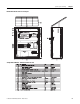
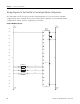
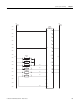
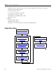
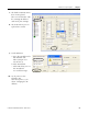
The AutoCAD electrical project includes wiring diagrams for each of the three DataSite
configurations. The example shows power wiring for the DataSite to ControlLogix Master
configuration. Add or remove components as needed.
Sample CAD Wiring Diagram
1001 1002
4
6
8
3
5
7
1001 1002
319
from 117 from 117
to 318
to 318
3111
3121
3131
1001 1002
+-
+-
+-
V-
AI5
AI4
AI3
AI2
AI1
AI0
DICOM
V+
DI0
DI1
DI2
DI3
DI4
DI5
DI6
DI7
+
WAKE UP
-
V-
GND
2
20
21
22
23
24
25
26
27
28
4
5
6
7
8
9
3
1
19
29
10
PS3111
PS3121
TS3131
TB1
TB1
TB1
TB1
TB1
TB1
RTU3011
1758-FLO302
DIFFERENTIAL PRESSURE
STATIC PRESSURE
TEMPERATURE
DATASITE
+12VDC 12VCOM
+12VDC
12VCOM
300
301
302
303
304
305
306
307
308
309
310
311
312
313
314
315
316
317