DataSite Accelerator Toolkit Quick Start Hardware Selection System Layout and Wiring DataSite and Logix Integration DataSite Workbench and Screen Builder Integration FactoryTalk View Integration System Validation
Important User Information Solid state equipment has operational characteristics differing from those of electromechanical equipment. Safety Guidelines for the Application, Installation and Maintenance of Solid State Controls (publication SGI-1.1 available from your local Rockwell Automation sales office or online at http://literature.rockwellautomation.com) describes some important differences between solid state equipment and hard-wired electromechanical devices.
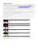
Where to Start Follow this path to complete your DataSite application.
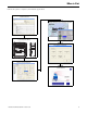
Where to Start DataSite Configurations This quick start shows how to set up and configure three functional DataSite configurations. • DataSite to ControlLogix master (Chapter 1 through 6) • DataSite to FactoryTalk View ME master (Appendix A) • DataSite to FactoryTalk View SE master with data logging capabilities (Appendix B) Chapter 1 through 6 cover the DataSite to ControlLogix Master configuration.
Where to Start The DataSite to FactoryTalk View ME Master configuration is good for small applications that don’t require a ControlLogix controller to poll multiple DataSite units. The PanelView Plus 600 terminal communicates with the DataSite unit using Modbus serial communication.
Where to Start 6 Publication IASIMP-QS008A-EN-P - March 2009
Table of Contents Preface About This Publication Software Requirements Conventions . . . . . . . . Additional Resources. . . . . . . . . . . . . . . . . . . . . . . . . . . . . . . . . . . . . . . . . . . . . . . . . . . . . . . . . . . . . . . . . . . . . . . . . . . . . . . . . . . . . . . . . . . . . . . . . . . . . . . . . . . . . . . . . . . 9 10 10 11 Introduction . . . . . . . . . . . . . . . . . . . . . Before You Begin . . . . . . . . . . . . . . . . . What You Need .
Table of Contents Chapter 5 FactoryTalk View Integration Introduction . . . . . . . . . . . . . . . . . . . . . . . . . . . . . . Before You Begin . . . . . . . . . . . . . . . . . . . . . . . . . . What You Need . . . . . . . . . . . . . . . . . . . . . . . . . . . Follow These Steps . . . . . . . . . . . . . . . . . . . . . . . . . Load and Restore FactoryTalk View ME Application . Configure Local Communication . . . . . . . . . . . . . . . Configure Target Communication . . . . . . . . . . . . . .
Preface About This Publication This quick start provides step-by-step instructions on how to set up and configure three functional DataSite configurations. • DataSite to a ControlLogix master (Chapter 1 through 6) • DataSite to a FactoryTalk View Machine Edition (ME) master (Appendix A) • DataSite to a FactoryTalk View Site Edition (SE) master with data logging capabilities (Appendix B) The examples are designed to get devices installed and communicating with each other in the simplest way possible.
Preface Software Requirements You need the following software to use this toolkit. Rockwell Automation Software Version DataSite Workbench 5.2 DataSite Screen Builder 1.3 DS FloConfig 1.0 RSLogix 5000 16 FactoryTalk View Studio, including: 5.0 • Machine Edition (ME) • Site Edition (SE) Conventions Proposal Works 6.1 Java Runtime Environment 6, Update 7 DataSite Accelerator Toolkit CD Not applicable This quick start uses the following conventions.
Preface Additional Resources Resource Description DataSite Natural Gas Flow Meter and Remote Terminal Unit Installation Instructions, publication 1758-IN001 Describes how to install and wire the Datasite unit. DataSite Electronic Flow Meter and Remote Terminal User Manual, publication 1758-UM001 Describes how to design, install, program, or troubleshoot control systems that use DataSite controllers.
Preface 12 Publication IASIMP-QS008A-EN-P - March 2009
Chapter 1 Hardware Selection Introduction In this chapter, you select the hardware for your application. You can select any of the three DataSite configurations covered in this quick start. Within each configuration, you have the option to purchase a pre-assembled DataSite panel or one that requires assembly. This chapter provides step-by-step instructions on how to use the Bill of Materials (BOM) provided with the DataSite Accelerator Toolkit CD.
Chapter 1 Hardware Selection Review Basic Panel Component Listings The bill of materials (BOM) on the DataSite Accelerator Toolkit CD includes the necessary components to duplicate the three DataSite configurations covered in this quick start. Review the component listings and compare with your specific application needs. Follow these steps to view the BOM on the DataSite Accelerator Toolkit CD for the DataSite to ControlLogix Master configuration. 1. Launch the DataSite Accelerator Toolkit CD. 2.
Hardware Selection Chapter 1 Proposal Works launches and displays the BOM for the DataSite to ControlLogix Master configuration. 4. Review the BOM and modify to fit your application. TIP Double-click a bolded part number to launch the configurator where you can modify components on the bill of material 5. After finalizing the BOM, click the Word icon on the toolbar to convert the BOM to a Word document. Word launches and displays the BOM. 6.
Chapter 1 16 Hardware Selection Publication IASIMP-QS008A-EN-P - March 2009
Chapter 2 System Layout and Wiring Introduction In this chapter, you plan the panel layout and wiring for your DataSite system. You can use the AutoCAD electrical drawings supplied on the DataSite Accelerator Toolkit CD to add or remove components in your DataSite system. Before You Begin Complete your system hardware selection (Chapter 1).
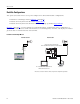
Chapter 2 System Layout and Wiring Follow These Steps Review DataSite Connections page 18 Plan Your DataSite Panel Layout and Wiring page 19 Verifying Your Basic Panel Layout page 20 Download Other Allen-Bradley CAD Drawings page 24 Review DataSite Connections Item Description Item Description 1 Discrete inputs and wake-up connectors 6 RS-485 COM 1 connector 2 Status indicators 7 Discrete output connectors 3 Ethernet connector 8 Power input and analog input connectors 4 RS-232 COM 2 con
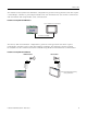
System Layout and Wiring Chapter 2 Plan Your DataSite Panel Layout and Wiring The DataSite Accelerator Toolkit CD includes AutoCAD Electrical project files that include panel layout and wiring diagrams that you can easily modify for your specific application. Individual DWG, DXF, and PDF files are available for use in standard AutoCAD and non-AutoCAD drawing and image software packages. The drawings are designed to optimize panel space and minimize electrical noise.
Chapter 2 System Layout and Wiring Verifying Your Basic Panel Layout The AutoCAD Electrical project includes panel layouts and wiring diagrams for each of the three DataSite configurations. Add or remove components as needed. Panel Layouts for the DataSite to ControlLogix Master Configuration The DataSite to ControlLogix Master configuration includes panel layouts for host and remote locations. Refer to the bill of material below each layout to review the items in each panel.
System Layout and Wiring Chapter 2 Remote DataSite Location - Panel Layout Sample Bill of Material - Remote DataSite Location Publication IASIMP-QS008A-EN-P - March 2009 21
Chapter 2 System Layout and Wiring Wiring Diagrams for the DataSite to ControlLogix Master Configuration The AutoCAD electrical project includes wiring diagrams for each of the three DataSite configurations. The example shows power wiring for the DataSite to ControlLogix Master configuration. Add or remove components as needed.
System Layout and Wiring 318 1001 from 317 +12VDC Chapter 2 1002 from 317 12VCOM DATASITE RTU3011 1758-FLO302 319 15 VDO+ 16 VDO- 320 11 DO0 321 12 DO1 322 13 DO2 323 14 DO3 40 AOV+ 324 325 41 AOV- 42 AO0 326 43 AOVHART DEVICE 1 SW3271 1001 327 9 TB1 328 11 TB1 + 1002 - 10 TB1 - 12 TB1 - 14 TB1 3271 - 16 TB1 3301 - 18 TB1 3311 + 20 TB1 3321 44 AO1 HART DEVICE 2 SW3281 + 45 AOV- HART DEVICE 3 SW3291 329 13 TB1 + 30 H0+ 31 H0- 32 H1+ 33 H1- 34 H2+ 35 H
Chapter 2 System Layout and Wiring Download Other Allen-Bradley CAD Drawings Follow these steps to download other Allen-Bradley product CAD drawings. 1. Open your browser and go to http://ab.com/e-tools. The Configuration and Selection tools web page opens. TIP If you know the complete catalog number of your Allen-Bradley product, you can enter it here and click Submit. However, you need a complete catalog number string to get the configuration results. 2.
Chapter 3 DataSite and Logix Integration Introduction In this chapter, you configure the DataSite unit, download the ControlLogix user program, configure the ProSoft (MVI56-MNET) Modbus TCP/IP communication module, and connect all system devices. Before You Begin • Complete your system hardware selection (Chapter 1). • Complete your system layout and wiring (Chapter 2). • Load all DataSite software on your computer as listed in the Preface on page 10.
Chapter 3 DataSite and Logix Integration – Modbus TCP/IP communication module (MV156-MNET) from ProSoft Technology – PanelView Plus 1000 terminal – Two Ethernet RF radios – 1747-CP3 null-modem serial cable – One Ethernet crossover cable – Five Ethernet straight-through cables – Ethernet switch • Software: – DS FloConfig software – RSLogix 1000 software – DataSite Accelerator Toolkit CD, publication IASIMP-SP011 Follow These Steps Configure the DataSite Unit page 27 Configuring the Logix Controller Load a
DataSite and Logix Integration Chapter 3 Configure the DataSite Unit The communication parameters for the DataSite unit are configured using DS FloConfig software. The DataSite unit can communicate using either its serial or Ethernet port. This quick start uses the serial port to assign the DataSite unit an IP address of 192.168.10.93 and then changes to Ethernet communication.
Chapter 3 DataSite and Logix Integration 5. Create a new project. a. Enter a project name. b. Enter the directory where you want to store the project. This examples saves the project in the default directory. c. Click Create. 6. Click PC Communication. a. Select COM1 from the Type Select pull-down list. b. Click Apply. A message informs you that the Communication port opened successfully. c. Click OK.
DataSite and Logix Integration Chapter 3 7. Click Flo Communication, then click Upload. The screen refreshes with the existing IP address and serial port settings. 8. Click OK when you see Upload Successful. 9. Under Ethernet: a. Type the IP address for the DataSite unit. This example uses 192.168.10.93. b. Click Download. c. Click OK when you see the Download successful message. 10. Cycle power to the DataSite unit. You must power cycle when changing the IP address.
Chapter 3 DataSite and Logix Integration 11. Click PC Communication. a. Select UDP or TCP/Server from the Type Select pull-down list. b. Type the IP address, 192.168.10.93 that you just downloaded to the DataSite unit. c. Click Apply. d. Click OK when you see Communication port opened successfully. 12. Connect your computer to the DataSite unit using an Ethernet crossover cable. Ethernet Crossover Cable 13. Click Flo Communication. a. Verify the IP address is 192.168.10.93. b. Click Download. c.
DataSite and Logix Integration Chapter 3 Configuring the Logix Controller The sample Logix program on the DataSite Accelerator Toolkit CD provides the logic necessary to manipulate data coming from the Modbus TCP/IP communication module and makes it available to the ControlLogix L63 controller tags. Load and Open the Logix Application File Follow these steps to load and open the (.acd) Logix application file from the DataSite Accelerator Toolkit CD. 1.
Chapter 3 DataSite and Logix Integration Configure the ControlLogix Controller Properties Follow these steps to configure your ControlLogix L63 controller. 2. Connect your computer and 1756-ENBT Ethernet module to the Ethernet switch using Ethernet straight-through cables. ENBT ENBT Module 192.168.10.90 192.168.10.95 ProSoft 1756-L63 ControlLogix Controller with 1756-ENBT Ethernet/IP Module 1. Apply power to your ControlLogix chassis. Ethernet Straight-through Cables Ethernet Switch 3.
DataSite and Logix Integration Chapter 3 Configure ControlLogix Communication This procedure assumes that communication to the Logix controller is using the Ethernet port. It also assumes that your 1756-ENBT Ethernet/IP module has already been configured with an IP address of 192.168.10.90. For additional information, refer to the ControlLogix Controllers User Manual, publication 1756-UM051. Follow these steps to configure ControlLogix communication. 1.
Chapter 3 DataSite and Logix Integration 5. Enter the IP address of your Ethernet ENBT module and click OK. This example uses 192.168.10.90. 6. Click Close to close the Configure Drivers window. 7. Choose RSWho from the Communications menu. The RSWho window opens. 8. Expand AB_ETH_1, Ethernet until your 1756-L63 Logix controller is visible. 9. Verify that you can browse to your Logix controller in slot 0. 10. Minimize the RSLinx window and return to your RSLogix 5000 project window.
DataSite and Logix Integration Chapter 3 4. Browse to the 1756-L63 controller and click the Set Project Path button. 5. Verify that the key switch on the controller is in the REM (remote) position. 6. Click Download. The Download window opens. 7. Click Download to send the program to the 1756-L63 controller. 8. Click No when the download is complete.
Chapter 3 DataSite and Logix Integration IMPORTANT All system devices must be configured and connected before placing the controller in Run mode. If the controller is already in Run mode, choose Offline from the Communications menu. Configure the ProSoft Modbus Module The ProSoft MV156-MNET Modbus TCP/IP communication module polls the Modbus registers of the DataSite unit and makes the data available to the 1756-L63 controller tags.
DataSite and Logix Integration Chapter 3 Follow these steps to download the WATTCP.CFG and MNET.CFG configuration files from the DataSite Accelerator Toolkit CD to the ProSoft Modbus module. 1. On the toolkit CD, choose DataSite to ControlLogix Master>ProSoft Interface Module Files, then copy the files MNET.CFG and WATTCP.CFG to your desktop. ProSoft Module, Slot 2 192.168.90.94 ENBT Slot 2 Publication IASIMP-QS008A-EN-P - March 2009 To Serial COM Port To CFG (RJ45) Port 3.
Chapter 3 DataSite and Logix Integration 5. Choose Start>Programs>Accessories>Communications>HyperTerminal to open the hyper terminal on your desktop. 6. Click No if you see this dialog box. 7. Enter a name for the new connection and click OK. 8. Select the COM port used by your computer and click OK. This example uses COM1.
DataSite and Logix Integration Chapter 3 9. Set the COM1 port settings as shown and click OK. 10. Press Shift+? to display the MVI56-MNET menu. 11. Press R, then press Y to transfer the MNET.CFG file. TIP After pressing Y, you have limited time to browse for the file before a timeout occurs. 12. From the Transfer menu, choose Send File.
Chapter 3 DataSite and Logix Integration 13. From the Send File dialog box: a. Click Browse to locate MNET.CFG, then click Open. b. Select Zmodem from the Protocol list. c. Press Send. A progress bar shows the status of the file transfer. 14. Press Shift+? to return to the main menu. 15. Press Shift+@, then Shift+? to display the Network menu. 16. Press R, then Y to transfer WATTCP.CFG. TIP After pressing Y, you have limited time to browse for the file before a timeout occurs. 17.
DataSite and Logix Integration Chapter 3 18. From the Send File dialog box: a. Click Browse to locate WATTCP.CFG, then click Open. b. Select Zmodem from the Protocol list. c. Press Send. A progress bar shows the status of the transfer. 19. Press Shift+? to display the Network menu; then press M followed by Shift+? to return the main menu. The ProSoft Modbus module is now configured. 20. Close the HyperTerminal dialog box. 21.
Chapter 3 DataSite and Logix Integration Connecting All Devices At this point all devices should be connected as shown in the illustration. Modify any previous connections, if necessary, to match the illustration.
Chapter 4 DataSite Workbench and Screen Builder Integration Introduction In this chapter, you download the DataSite Workbench sample user program and DataSite Screen Builder sample web pages to the DataSite unit. Before You Begin • Complete your system hardware selection (Chapter 1). • Complete your system layout and wiring (Chapter 2). • Complete the DataSite and Logix Integration (Chapter 3). • Verify that all devices are connected properly and are powered up.
Chapter 4 DataSite Workbench and Screen Builder Integration Follow These Steps Download the DataSite User Program page 45 Download the DataSite Web Pages page 49 44 Publication IASIMP-QS008A-EN-P - March 2009
DataSite Workbench and Screen Builder Integration Chapter 4 Download the DataSite User Program Follow these steps to compile and download the sample DataSite user program. 1. Launch DataSite Workbench 5.2 software. 2. From the Project/Library menu, choose Open. 3. Select the Prj folder from the Look in: pull-down list. 4. Double-click the folder DataSite_Base_Program. If you don’t see this dialog box, refer to the tip. TIP If you don’t see the DataSite_Base_Program folder in step 4, follow these steps.
Chapter 4 DataSite Workbench and Screen Builder Integration 5. Double-click PrjLibary.mdb to open the user program. 6. Click the Hardware Architecture button. 7. Double-click the Vertical Network Bar, then enter the IP address of the DataSite unit and click OK.
DataSite Workbench and Screen Builder Integration Chapter 4 8. Click the Link Architecture button. 9. Click Rebuild Project/Library. 10. Verify there are no errors. 11. Click the Download button to download the program to the DataSite unit. 12. Click Select All, then click Download.
Chapter 4 DataSite Workbench and Screen Builder Integration TIP If the DataSite unit is running a program, you will see a message similar to the one below. Click Stop and Download to complete the Download process. The DataSite Workbench user program has been downloaded and is running on the DataSite unit.
DataSite Workbench and Screen Builder Integration Chapter 4 Download the DataSite Web Pages You will now compile and download the sample DataSite web pages to the DataSite unit. Follow these steps to download the HiBeam web pages. 1. Launch the DataSite Screen Builder 1.3 software. 2. From the File menu, choose Open. 3. Select the Prj folder from the Look in: pull-down list. 4. Double-click the folder DataSite_Base_Web_Pages. If you don’t see this dialog box, refer to the tip.
Chapter 4 DataSite Workbench and Screen Builder Integration 5. Double-click DataSite_Base_Web_Pages.HAD to open the web page program. 6. From the toolbar, choose Project>Settings. 7. On the Project tab, click the Path browse button. 8. Browse to the DataSite Workbench default project directory. Default DataSite Workbench project directory: C:\Documents and Settings\All Users\Documents\DataSite\Projects\Workbench 5.
DataSite Workbench and Screen Builder Integration Chapter 4 11. Click the Data Servers tab. a. Double-click the row to select the IP address of the DataSite unit. b. Click OK. 12. Click the Compile button. 13. Verify there are no errors. 14. Click the Download button. 15. Click Options.
Chapter 4 DataSite Workbench and Screen Builder Integration 16. Check Send Java Classes and click OK. TIP Checking the Send JAVA classes box is only required the first time you download a project. Subsequent downloads do not require you to check this box. 17. Load the web pages. a. Select the IP address of the DataSite unit. b. Click the Load button. Wait two to three minutes to complete the download process. c. Click Close when you see the message Connection OK.
Chapter 5 FactoryTalk View Integration Introduction In this chapter, you download the FactoryTalk View ME project to a PanelView Plus 1000 terminal connected to a ControlLogix 1756-L63 controller. Before You Begin • Complete your system hardware selection (Chapter 1). • Complete your system layout and wiring (Chapter 2). • Complete the DataSite and Logix Integration (Chapter 3). • Complete the DataSite Workbench and Screen Builder integration (Chapter 4).
Chapter 5 FactoryTalk View Integration Follow These Steps Load and Restore FactoryTalk View ME Application page 54 Configure Local Communication page 56 Configure Target Communication page 59 Download Project to PanelView Plus Terminal page 61 Run the Project on PanelView Plus Terminal page 64 Load and Restore FactoryTalk View ME Application Follow these steps to load and restore the FactoryTalk View Machine Edition (ME) application from the DataSite Accelerator Toolkit CD using the Application Manager.
FactoryTalk View Integration Chapter 5 The Application Manager window opens. 2. Select Restore the FactoryTalk View Machine Edition application and click Next. 3. Type DataSite_ME_CLX as the application name and click Finish. The Application Manager closes after it restores the application.
Chapter 5 FactoryTalk View Integration Configure Local Communication The Design (Local) tab in Communications Setup reflects the view of the topology from the RSLinx Enterprise server on the development computer. In this example, the development computer is communicating to a ControlLogix L63 controller via Ethernet communication. Follow these steps to configure local communication. 1. Apply power to your ControlLogix L63 controller. 2.
FactoryTalk View Integration Chapter 5 4. Select DataSite_ME_CLX from the Existing tab and click Open. The Machine Edition application opens. 5. Expand RSLinx Enterprise in the Explorer window. 6. Double-click Communication Setup.
Chapter 5 FactoryTalk View Integration The Communication Setup window opens. 7. Select L63 under Device Shortcuts. 8. Click Remove then click Yes to verify the removal of the shortcut. 9. Expand the RSLinx Enterprise tree to access your 1756-L63 controller in slot 0 (0, 1756-L63). 10. Click Add under Device Shortcuts. 11. Enter L63 as the shortcut name and press Enter. 12. Select your Logix controller 0, 1756-L63. 13. Click Apply under Device Shortcuts. 14. Click Yes to apply changes.
FactoryTalk View Integration Chapter 5 Configure Target Communication The Runtime (Target) tab displays the offline configuration from the perspective of the device that is running the application and comprises the topology that is loaded in the PanelView Plus terminal. In this example, the PanelView Plus terminal communicates to the same ControlLogix L63 controller via Ethernet communication. Follow these steps to configure target communication. 1.
Chapter 5 FactoryTalk View Integration 4. Select the Runtime (Target) tab and expand the RSLinx Enterprise tree. 5. Click the L63 shortcut to verify that your controller and shortcut name are both highlighted. In this example, 1756-L63 is the controller in slot 0 and L63 is the shortcut name. 6. Click OK at the bottom right corner of the window.
FactoryTalk View Integration Chapter 5 Download Project to PanelView Plus Terminal Follow these steps to create a FactoryTalk View ME runtime file and download it to the PanelView Plus terminal. 1. Choose Create Runtime Application from the Application menu. The Create Runtime Application dialog box opens. 2. Select Runtime 5.0 Application (*.mer) from the Save as type list. 3. Type DataSite_ME_CLX.mer in the File name field. 4. Click Save and wait for the progress bar to complete. 5.
Chapter 5 FactoryTalk View Integration The Transfer Utility opens. 6. Click the Browse ... button to locate the runtime file. 7. Select DataSite_ME_CLX.mer from the Runtime folder. Default Runtime folder path: C:\Documents and Settings\All Users\Documents\RSView Enterprise\ME\Runtime 8. Click Open.
FactoryTalk View Integration Chapter 5 9. Browse and select your PanelView Plus terminal, then click Download. TIP If the PanelView Plus terminal has an existing .mer file with the same name, click Yes to overwrite the file. 10. Click OK when the download completes successfully. 11. Click Exit to close the File Transfer Utility. 12. Choose Exit from the File menu to close the FactoryTalk View Studio software.
Chapter 5 FactoryTalk View Integration Run the Project on PanelView Plus Terminal The (.mer) runtime file is now stored in the PanelView Plus terminal so you are ready to run the project on the terminal. Follow these steps to run your project on the PanelView Plus terminal. 1. Verify that the PanelView Plus is connected as shown on page 42 and that it is receiving power. 2. Press Load Application [F1] in the FactoryTalk View ME Station dialog box. The Load Application dialog box opens. 3.
FactoryTalk View Integration Chapter 5 5. Press Yes [F7]. If you press No, the communication settings from the previously run project will be used. 6. Wait for the application to the load and verify that DataSite_ME_CLX.mer appears under Current application. 7. Press Run Application [F2]. The application builds and displays a DataSite screen on the PanelView Plus terminal. Refer to Chapter 6 for system validation.
Chapter 5 66 FactoryTalk View Integration Publication IASIMP-QS008A-EN-P - March 2009
Chapter 6 System Validation Introduction In this chapter, you validate the DataSite system by verifying that all AGA flow data can be seen on the PanelView Plus 1000 terminal and on the DataSite web pages. Before You Begin • Complete your system hardware selection (Chapter 1). • Complete your system layout and wiring (Chapter 2). • Complete the DataSite and Logix Integration (Chapter 3). • Complete the DataSite Workbench and Screen Builder integration (Chapter 4).
Chapter 6 System Validation Follow These Steps Validate DataSite to PanelView Plus Communication page 69 Validate DataSite Web Pages page 75 Review DataSite Workbench User Program page 80 68 Publication IASIMP-QS008A-EN-P - March 2009
System Validation Chapter 6 Validate DataSite to PanelView Plus Communication You are now ready to validate communication between the DataSite unit and the PanelView Plus terminal. Using the DS FloConfig software, you will simulate three process variables and validate that the calculated flow values display on the PanelView Plus terminal. TIP To use actual process variables, wire temperature, pressure, and differential pressure transmitters to the DataSite analog inputs.
Chapter 6 System Validation 3. Select MeterRun0 on the left side of the dialog box. 4. Click Calculation Test and check all three boxes. a. Type 800 for Static Pressure. b. Type 80 for Temperature. c. Type 70 for Differential Pressure. d. Click OK. TIP 70 You can optionally repeat steps 3 and 4 for Meter Run1 through Meter Run7.
System Validation Chapter 6 5. Click OK when you see the message Download Successful. 6. Expand Meter Run0, select Field Parameters, then click Upload. 7. Check Accumulate and click Download. 8. Return to the RSLogix 5000 software. 9. Choose Online from the Communication menu and place your L63 ControlLogix controller in Run mode. 10. Verify the FactoryTalk View ME project is running on the PanelView Plus 1000 terminal.
Chapter 6 System Validation 11. Press Meter Run 0 on the PanelView Plus terminal. 12. Verify the Meter Run 0 process variables are the same as DS FloConfig on the next page.
System Validation Chapter 6 DS FloConfig Process Variables 13. Press Return to Main Screen on the PanelView Plus terminal. TIP You can optionally repeat steps 9 through 12 to validate the process variables for Meter Run 1 through Meter Run 7.
Chapter 6 System Validation 14. Press DS Digital Outputs on the main PanelView screen to validate control of the DataSite digital outputs. 15. Press a digital output. The push button on the left turns ON digital output 0. The push button on the right turns ON digital output 1.
System Validation TIP Chapter 6 To verify this functionality, you must wire a testing device such as a stack light into digital output 0 and another device into digital output 1. You must also supply the required voltage to terminals DOV+ and DOV-. The configuration and validation of the Data Site unit to ControlLogix Master is now complete.
Chapter 6 System Validation 2. Launch Internet Explorer. 3. In the Address bar, type http://192.168.10.93/datasite.html IMPORTANT You must enter the correct IP address of the DataSite unit. This quick start uses 192.168.10.93 Java takes about one minute to load this screen. Similar to the PanelView Plus terminal, the web pages will display the same flow data as in DS FloConfig. 4. Click Meter Run 0.
System Validation Chapter 6 5. Verify the process variables are the same as in DS FloConfig. 6. Click Main Menu to return to the main application screen.
Chapter 6 System Validation 7. Click Digital Outputs. 8. Click Digital Output 2.
System Validation TIP Chapter 6 To verify this functionality, you must wire a testing device such as a stack light into digital output 2 and another device into digital output 3. You must also supply the required voltage terminals DOV+ and DOV-. 9. Repeat the previous step to verify Digital Output 3. You just completed web page validation. Modify the existing sample programs to meet your application needs. This example only displays data for one meter run.
Chapter 6 System Validation Review DataSite Workbench User Program The sample DataSite Workbench project consists of four programs. • Power Save - Saves power by turning power on/off to the LEDs, serial port, and RS485 port. • Screen Builder Variables - Reads Meter Run 0 flow data variables and assigns a DataSite Workbench variable that can be used by the DataSite web pages. • Digital Outputs - Controls DataSite digital outputs 2 and 3.
Appendix A DataSite to FactoryTalk View ME Master This appendix describes how to configure a PanelView Plus 600 terminal to communicate with the DataSite using Modbus serial communication. This setup requires KEPServerEnterprise V4.0 to configure drivers between the DataSite unit and the PanelView Plus terminal running FactoryTalk View ME.
Appendix A DataSite to FactoryTalk View ME Master – 2711C-NC13 serial cable – 2711P-CBL-EX04 Ethernet crossover cable • Software: – KEPServerEnterprise V4.
DataSite to FactoryTalk View ME Master Appendix A Load KEPServerEnterprise File Follow these steps to load a KEPServer Enterprise .pfe file that contains Modbus addresses of the parameters to be polled and displayed on the PanelView Plus 600 HMI terminal. 1. From the DataSite Accelerator Toolkit CD, choose DataSite to FactoryTalk View ME Master>HMI Application files. 2. Copy ModbusSerial.pfe from the CD to the default project folder for KEPServerEnterprise.
Appendix A DataSite to FactoryTalk View ME Master 5. From the Tools menu, Choose Options. 6. Click the Browse ... button to locate the default project ModbusSerial.pfe. C:\Program Files\KEPServerEnterprise\Projects\ModbusSerial.pfe 7. Click Apply. 8. Click OK.
DataSite to FactoryTalk View ME Master Appendix A Load FactoryTalk View ME Application The FactoryTalk View ME application contains screens to display flow data on a PanelView Plus 600 terminal for one meter run. Follow these steps to load the FactoryTalk View ME application from the DataSite Accelerator Toolkit CD. 1. On the toolkit CD, choose DataSite to FactoryTalk View ME Master>HMI Application Files, then double-click DataSite_ME_Modbus_Serial.apa. The Application Manager window opens. 2.
Appendix A DataSite to FactoryTalk View ME Master 3. Type DataSite_ME_Modbus_Serial as the application name, then click Finish. DataSite_ME_Modbus_Serial The Application Manager closes after it restores the application. 4. Launch FactoryTalk View Studio software. 5. If this dialog box opens, select Machine Edition and click Continue.
DataSite to FactoryTalk View ME Master Appendix A 6. Select DataSite_ME_Modbus_Serial from the Existing tab and click Open. The FactoryTalk View ME application opens. 7. Create the .mer file and download to the PanelView Plus 600 terminal. TIP Refer to Download Project to PanelView Plus Terminal on page 61 for details on how to create a runtime application and download the .mer application file to the PanelView Plus 600 terminal.
Appendix A DataSite to FactoryTalk View ME Master Validate Communication Between DataSite and Terminal You are now ready to run the .mer application on the PanelView Plus 600 terminal, and validate communication with the DataSite unit. The KEPServer (.pfe) file polls 19 parameters for one meter run and displays the data on the PanelView Plus 600 terminal. TIP The validation assumes that AGA calculations were initiated using instrumentation devices or simulated in DS FloConfig.
DataSite to FactoryTalk View ME Master Appendix A The Load Application dialog box opens. 3. Use the up/down arrows to scroll through the list of applications and select DataSite_ME_Modbus_Serial. 4. Press Load [F2]. 5. Press Yes [F7]. If you press No, the communication settings from the previously run project will be used.
Appendix A DataSite to FactoryTalk View ME Master 6. Wait for the application to the load and verify that DataSite_ME_Modbus_Serial. mer appears under Current application. 7. Press Run Application [F2]. The application builds and displays a DataSite screen on the PanelView Plus terminal. 8. Press Process Variables & Compressibility.
DataSite to FactoryTalk View ME Master Appendix A Select a Different COM Port for the Serial DF1 Driver If the variable data appears as asterisks on the PanelView Plus terminal, you need to change the COM port used by the serial DF1 driver. If data appears correctly on the terminal, you can skip this section. Follow these steps to select a different COM port for the serial DF1 driver. 1. Press Terminal Settings [F4] in the FactoryTalk View ME Station dialog box. 2.
Appendix A DataSite to FactoryTalk View ME Master 3. Select RSLinx Enterprise Communications by pressing the cursor key, then press the Enter button. 4. Select Serial-DF1, then press Edit Driver [F2].
DataSite to FactoryTalk View ME Master Appendix A 5. Select COM Port, then press Edit [F1]. 6. Select 2, then press OK [F7].
Appendix A DataSite to FactoryTalk View ME Master 7. Press the Cancel [F8] button until you return to the main menu. 8. Repeat steps 2 through 8 starting on page 88 to validate the application.
Appendix B DataSite to FactoryTalk View SE Master This appendix shows how to configure an industrial computer running FactoryTalk View SE software to communicate with a DataSite unit using Modbus TCP/IP communication. This setup requires KEPServerEnterprise software V4.0 to configure the communication driver.
Appendix B DataSite to FactoryTalk View SE Master What You Need • Hardware: – DataSite unit – 6181P industrial computer or personal computer – Two radios, optional – Two 2711P-CBL-EX04 Ethernet crossover cables • Software: – KEPServerEnterprise V4.
DataSite to FactoryTalk View SE Master Appendix B Load KEPServerEnterprise File Follow these steps to load a KEPServer Enterprise .pfe file that contains Modbus addresses of the parameters to be polled and displayed on the industrial computer. 1. From the DataSite Accelerator Toolkit CD, choose DataSite to FactoryTalk View SE Master>HMI Application Files. 2. Copy ModbusEthernet.pfe from the CD to the default project folder for KEPServerEnterprise. C:\Program Files\KEPServerEnterprise\Projects 3.
Appendix B DataSite to FactoryTalk View SE Master 5. Choose Options from the Tools menu. 6. Click the Browse button ... to locate the default project ModbusEthernet.pfe. C:\Program Files\KEPServerEnterprise\Projects\ModbusEthernet.pfe 7. Click Apply. 8. Click OK.
DataSite to FactoryTalk View SE Master Appendix B Load FactoryTalk View SE Application The FactoryTalk View SE application contains a screen that controls when to start and stop data logging to an Excel file. It also contains a screen with gas flow data for Meter Run 0. Follow these steps to load the FactoryTalk View SE application from the DataSite Accelerator Toolkit CD. 1.
Appendix B DataSite to FactoryTalk View SE Master The Application Manager window opens. 2. Select Restore the FactoryTalk View SE (local) application, then click Next. 3. Enter DataSite_ME_Modbus_Ethernet as the application name and click Finish. DataSite_ME_Modbus_Ethernet The Application Manager closes after it restores the application.
DataSite to FactoryTalk View SE Master Appendix B 4. Launch FactoryTalk View Studio software. 5. If this dialog box opens, select Site Edition (Local) and click Continue. 6. Select DataSite_SE_Modbus_Ethernet from the Existing tab and click Open. The FactoryTalk View SE application opens.
Appendix B DataSite to FactoryTalk View SE Master 7. Click Launch SE Client on the toolbar. 8. Click New. 9. Click New.
DataSite to FactoryTalk View SE Master Appendix B 10. Enter DataSite_Client as the configuration file name, then click Next. 11. Select Local, then click Next.
Appendix B DataSite to FactoryTalk View SE Master 12. Select DataSite_SE_Modbus_Ethernet from the pull-down list or the name of the application assigned during the restore, then click Next. 13. Select Main from the Initial Display pull-down list, then click Next.
DataSite to FactoryTalk View SE Master Appendix B 14. Enter DataSite as the Title bar text and click Next. 15. Click Next.
Appendix B DataSite to FactoryTalk View SE Master 16. Select Save configuration and open FactoryTalk View SE Client now and click Finish. Factory Talk View SE Client launches the application. Continue to the next section to validate communication and perform data logging. Validate Communication Between DataSite and Computer You are now ready to validate communication between the DataSite unit and the industrial computer. 1. Press Meter Run.
DataSite to FactoryTalk View SE Master Appendix B You should see a screen with gas flow values for Meter Run 0. 2. Verify the process variables are correct and press Main Menu. 3. Press Data Logging. 4. Press Datalog ON. 5. Allow data logging to run for about one or two minutes, then press Datalog OFF.
Appendix B DataSite to FactoryTalk View SE Master 6. On the toolkit CD, choose DataSite to FactoryTalk View SE Master>HMI Application files, then double-click RSView Enterprise File Viewer. 7. From the File menu, choose Open. 8. Drill down to the datalog folder and double-click it.
DataSite to FactoryTalk View SE Master Appendix B 9. Select the file with the latest date, where the format of the file name is YYYY MM DD 0000 (Float).DAT. A file similar to this displays. 10. From the File menu, choose Save As.
Appendix B DataSite to FactoryTalk View SE Master 11. Enter a file name, then click Save. The file is saved in a .csv format for viewing in Excel. 12. Go to your desktop and locate the file just created. 13. Double-click MeterRun0_Flow_Data.csv to view the data in Microsoft Excel. 14. View and manipulate the data if necessary. You have just completed the setup and validation of the DataSite to Master SE configuration.
Rockwell Automation Support Rockwell Automation provides technical information on the Web to assist you in using its products. At http://support.rockwellautomation.com, you can find technical manuals, a knowledge base of FAQs, technical and application notes, sample code and links to software service packs, and a MySupport feature that you can customize to make the best use of these tools.