Quick Start Getting Started with ProcessLogix R400.
Getting Started with ProcessLogix R400.0 Important User Information Because of the variety of uses for the products described in this publication, those responsible for the application and use of these products must satisfy themselves that all necessary steps have been taken to assure that each application and use meets all performance and safety requirements, including any applicable laws, regulations, codes and standards.
Getting Started with ProcessLogix R400.0 3 Rockwell Automation Technical Support If you need any assistance with the information found in this document, first call your local Rockwell Automation representative, then: • Phone Support: (440) 646-5800 • Web Support:http://www.ab.
Getting Started with ProcessLogix R400.0 Starting the Software In this section, we explain how to start: • The ProcessLogix R400.0 Server software • Control Builder software TIP The System Repository is the database that contains information about your control environment. The CDA program controls communications between ProcessLogix server applications and RSLinx communication software. The System Repository and the CDA program are both Windows 2000 Services that start automatically.
Getting Started with ProcessLogix R400.0 5 Verify the ControlNet Nodes Using NTools (Network Tools): 1. To view chassis configuration, click Start⇒Programs⇒ProcessLogix Engineering Tools⇒NTools. 2. Click OK to acknowledge the warning. 3. Click NetworkTools⇒Settings. 4. Select the Ping option and click OK. 5. Click NetworkTools⇒Ping. 6. Click the CNB with Network Address 1. This can be found under the Desktop tree icon in the upper left window. 7.
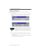
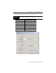
Getting Started with ProcessLogix R400.0 Starting the ProcessLogix Server The ProcessLogix Server program is the operating system for the ProcessLogix Server. To start the Server: 1. Click Start⇒Programs⇒ProcessLogix Server⇒Start-Stop ProcessLogix Server to call up the ProcessLogix Server dialog box. Check that the Server is running.
Getting Started with ProcessLogix R400.0 7 Turning Off Areas Areas are portions of a process you wish to control. This Quick Start assumes that Areas are turned off. To turn off areas: 1. Click Start⇒Programs⇒ProcessLogix Server⇒Station. 2. Select Configure⇒Areas⇒Areas. 3. Access manager mode. a. Click Oper in the bottom right of the screen. b. In the Station Logon dialog box, type mngr. c. Click OK. Oper changes to Mngr. 4. To disable areas, uncheck the Areas Enabled check box. 5. Exit Station.
Getting Started with ProcessLogix R400.0 2. Enter mngr (lowercase) for your User Name and mngr1 (lowercase) for your Password, and click OK. 3.
Getting Started with ProcessLogix R400.0 9 2. In the CPM Parameters dialog box, select the following: IMPORTANT Be careful to enter the CPM Parameters correctly. You will not be able to change them after they are entered.
Getting Started with ProcessLogix R400.0 3. Click OK to close the CPM Parameters dialog box. 4. To see your newly configured CPM and CEE, click the Project tab. TIP To see the CPM and CEE, you may need to expand the Root branch of your tree by clicking the small “+” sign to the left of the word Root. The CEE is listed under the CPM and is connected directly to it. This tells you that the CEE is assigned to the CPM. 5. Load the CPM and the CEE: a. In the project tab, click CPM0101. b.
Getting Started with ProcessLogix R400.0 11 Configuring I/O Modules Once you have created a controller, the next step is to configure the I/O modules you will use in your system. Before you can configure a module, you must add it from the library to your project: 1. Click the Library tab. 2. Click the + to the left of the IO icon to see a list of available modules. 3.
Getting Started with ProcessLogix R400.0 TIP In the Project tab, you can see the modules displayed under Root. Configuring analog input modules To configure an analog input module: 1. Double-click the IOM with the name LabAI. This brings up the window for the 6-channel isolated analog input module (1756-IF6I). 2.
Getting Started with ProcessLogix R400.0 13 Configuring analog output modules To configure an analog output module: 1. Double-click the IOM named LabAO. This brings up the window for the 6-channel isolated analog output module (1756-OF6CI; current output, or 1756-OF6VI; voltage output). 2.
Getting Started with ProcessLogix R400.0 2. On the IOM Configuration window, select the Main tab and enter the following parameters: in this field: enter: IOM Slot Number the slot number containing this module Remote I/O Chassis Mac Address 0 ControlNet Modulel Slot Number 0 3. Select the Module Configuration tab. 4. In the Filter Times fields, select 1MSDELAY for all channels. 5. Click OK. Configuring digital output modules To configure a digital output module: 1.
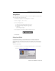
Getting Started with ProcessLogix R400.0 15 Assigning Modules to a Controller Execution Environment Once you have configured I/O modules, you must assign them to the controller execution environment (CEE). To assign modules to the CEE: 1. From Control Builder, select Tools⇒Assign. You see the Controller Assignments window: 2. Click the IOMs tab in the Available Modules area. 3. To select all four modules, click the first module, hold down the Shift Key, and click the last module. 4.
Getting Started with ProcessLogix R400.0 7. Locate the Labx I/O modules in the CEE0101 folder of the Project tab. TIP To locate the IOMs, you may need to expand the CEE and I/O branches of the tree in the Project tab. 8. Load the IOMs by doing the following: a. Select all of the IOMs in the I/O list area. ATTENTION ! Load only the I/O modules that physically exist in the chassis. b. Click the green down arrow (load) in the toolbar. The Load dialog box appears. c.
Getting Started with ProcessLogix R400.0 17 Creating a PID Loop The next step is to create a Control Module to control a process. In this example, we create a PID loop. Creating the Control Module To create the Control Module: 1. Click File⇒New⇒Control Module. You see a blank window for the Control Module in the center of your screen. 2. Rename the Control Module: a. Double-click anywhere in the CM Window. You see the Parameter window. b. In the Name field, enter FIC102. 3.
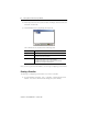
Getting Started with ProcessLogix R400.0 Assigning the Control Module to the Controller Execution Environment To assign the Control Module for the PID loop to the CEE: 1. From Control Builder, select Tools⇒Assign. 2. On the Controller Assignments window, click the CMs/SCMs tab in the in the Available Modules box. 3. Select FIC102 from the Available Modules box. 4. Select the CEE0101 from the CEE/Link box and click Assign. The FIC102 module is displayed in the Assigned Modules box. 5.
Getting Started with ProcessLogix R400.0 19 Wire the blocks IMPORTANT The Numeric block you created enables you to simulate a control loop. For this loop to work properly, do not wire the AICHANNEL block. Adjust your blocks to look similar to the window below. 1. Double-click the source wire. The cursor changes to a “+”. 2. Click the destination wire. TIP For additional wire segments as you draw your wire, click the left mouse button.
Getting Started with ProcessLogix R400.0 Configure parameters 1. Double-click the NUMERIC block. You see the Numeric Parameters window. 2. Enter 10 in the Actual Value field. 3. Click OK. 4. Double-click the PID block. You see the PID Parameters window. 5. Click the Algorithm tab. 6. Enter these parameters: in this field: enter: T1 0.1 T1 High Limit 2 High Gain Limit 2 Overall Gain 0.5 7. Click OK. 8. Double-click the AICHANNEL block. You see the AICHANNEL Parameters window. 9.
Getting Started with ProcessLogix R400.0 21 Enter Alarms 1. Double-click the DATACQ block to display the Parameters window. 2. Click the Alarms tab. 3. Enter these alarms: IMPORTANT You must enter the PV High alarm first to enable the PV High High alarm. type trip point priority severity PV High 85 High 0 PV High High 95 Urgent 0 4. Click OK. 5. Close the Control Module FIC102. 6. When prompted, click Yes to save changes.
Getting Started with ProcessLogix R400.0 Changing the Controller Execution Environment for the 1757-PLX52 Control Processor Module from Inactive to Active To execute your program, you must change the CEE and CM from inactive to active. Follow these steps to change the CEE, CM, and IOMs to active: 1. In the Monitoring tab, click CEE0101. 2. Select Operate⇒Activate⇒This CEE and its IOMs and CMs. 3. Click Yes to change the state of the selected objects.
Getting Started with ProcessLogix R400.0 23 10. Verify that the PID OP output value (displayed near the wire) changes. 11. Change the NUMERIC.PV to 20, then 30. 12. Click Yes when prompted to Change Online Value and click OK. Observe the OP output of the PID block for changes. 13. Close the diagram without saving your changes. Viewing Pre-built Screens To view the pre-built screens provided with the ProcessLogix system: 1.
Allen-Bradley, ProcessLogix, and RSLinx are trademarks of Rockwell Automation Windows 2000 is a registered trademark of Microsoft Corporation Publication 1757-QS040A-EN-P - October 2001 PN 957555-53 Copyright © 2001 Rockwell Automation. All rights reserved. Printed in the U.S.A.