
User Manual Manual


Rockwell Automation Publication 1757-UM012A-EN-P - July 2011 77
Chapter
5
Create an RSLogix 5000 Software Project
Introduction
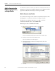
This section describes how to set up a linking device with a Logix5000 controller
by using the RSLogix 5000 software. Examples show the 1757-FFLD linking
device but procedures are similar for the 1757-FFLDC linking device, which
bridges H1 field devices to Logix controllers via the ControlNet network.
Ethernet - 1757-FFLD
Linking Device Example
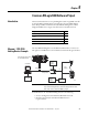
The 1757-FFLD linking device uses the Ethernet/IP network to connect to an
H1 segment so fieldbus devices can communicate with ControlLogix controllers.
In this illustration, the 1757-FFLD linking device does the following:
• Serves as a bridge between the EtherNet/IP and H1 networks.
• Provides connectivity for Foundation Fieldbus devices to
Logix controllers.
Topic Page
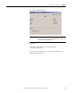
Create a Project for the Controller 78
Add the Communication Module, Linking Device, and Logix
Blocks
80
Schedule the ControlNet Network 93
Electronic Keying 94
ControlLogix Controller with
the 1756-ENBT Module
Ethernet/IP
RSFieldbus
OPC
OPC Client
24V DC
Power
Supply
1757-FFLD
Linking Device
H1
Power
Conditioner
44428
Field
Devices
24V DC
Power
Supply
IMPORTANT
Rockwell Automation does not support the 1757-FFLD and
1757-FFLDC linking devices communicating with the same
HSE server in the same RSFieldbus project.