
User Manual Manual

148 Rockwell Automation Publication 1757-UM012A-EN-P - July 2011
Appendix A Troubleshoot the Linking Device
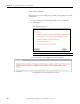
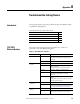
The table provides a description of the status indicators for channels on the
ControlNet network that are used along with the 1757-FFLDC linking device.
Alternating red/
green
Self-test None.
Incorrect channel
configuration
Verify that the ControlNet network is connected to
the correct channel of the linking device (for
example), if the ControlNet network is configured for
channel A only, then the linking device must be
connected to the network via channel A).
Alternating red/off Duplicate ControlNet
node address
• Choose a unique node address.
• Cycle power to the linking device.
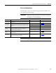
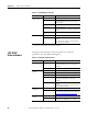
Table 15 - ControlNet Channel Troubleshooting (A AND B)
AND Cause Action
Off Channel disabled. Use RSNetwork for ControlNet software to
configure the ControlNet network for redundant
media, if required.
Solid green Normal operation None.
Flashing green/off Temporary network
errors
• Check media for broken cables, loose connectors,
or missing terminators.
• If condition persists, refer to the ControlNet
Media Planning and Installation Manual,
publication CNET-IN002
.
Flashing red/off Media fault • Check media for broken cables, loose connectors,
or missing terminators.
• If condition persists, refer to the ControlNet
Media Planning and Installation Manual,
publication CNET-IN002.
No other nodes
present on network
Add other nodes to the network.
Flashing red/green Incorrect ControlNet
node address
• Change linking device node address so that it is
less than or equal to UMAX.
(1)
• Cycle power to the linking device.
(1) UMAX is the highest node address on a ControlNet network than can transmit data.
Incorrect network
configuration
Use RSNetWorx for ControlNet software to
reconfigure the ControlNet network so that UMAX
(1)
is greater than or equal to the linking device’s
node address.
Table 14 - ControlNet Network Troubleshooting (A AND B)
AND Cause Action