
User Manual Manual

114 Rockwell Automation Publication 1757-UM012A-EN-P - July 2011
Chapter 7 Linking Device Function Blocks
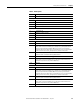
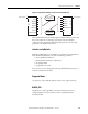
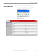
Table 7 - VCR Examples
Example Linking Device VCR Count Diagram
Basic input
device
1 input (PV) =
1 VCR (subscriber)
Total VCRs = 1 subscriber
Complex
input device
x inputs (PV) =
x VCRs (subscribers)
Total VCRs = x subscribers
Output
device
1 output (PV) =
1 VCR (publisher) +
1 VCR (subscriber) from BKCAL
2 inputs (PV) from Limit Switch =
2 VCRs (subscribers)
Total VCRs = 1 publisher
3 subscribers
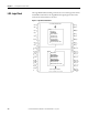
Pressure or
Temperature
Transmitter
Input
VCR 1
Linking Device
Logix
Block
Flowmeter
Input 1
Input 2
Input x
VCR 1
VCR 2
VCR x
Linking Device
Logix
Block
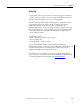
Linking Device
Logix
Block
VCR 1
VCR 2
BKCAL
VCR 3
VCR 4
Valve
Input 1
Output 1
Output 2
Limit Switch
Limit Switch