Installation Instructions Foundation Fieldbus Linking Device Catalog Numbers 1757-FFLD2, 1757-FFLD4 Topic Page Important User Information 2 Environment and Enclosure 3 North American Hazardous Location Approval 4 European Hazardous Location Approval 5 Parts Illustration of the Fieldbus Linking Device 6 Install the Linking Device 7 Wire the Linking Device 11 Configure the Linking Device 14 Troubleshoot the Linking Device 18 Specifications 21 Additional Resources 26 About the Fieldbus
Foundation Fieldbus Linking Device Important User Information Solid state equipment has operational characteristics differing from those of electromechanical equipment. Safety Guidelines for the Application, Installation and Maintenance of Solid State Controls (Publication SGI-1.1 available from your local Rockwell Automation sales office or online at http://www.literature.rockwellautomation.com) describes some important differences between solid state equipment and hard-wired electromechanical devices.
Foundation Fieldbus Linking Device 3 Environment and Enclosure ATTENTION This equipment is intended for use in a Pollution Degree 2 industrial environment, in overvoltage Category II applications (as defined in IEC 60664-1), at altitudes up to 2000 m (6562 ft) without derating. This equipment is considered Group 1, Class A industrial equipment according to IEC/CISPR 11.
Foundation Fieldbus Linking Device North American Hazardous Location Approval The following information applies when operating this equipment in hazardous locations. Informations sur l’utilisation de cet équipement en environnements dangereux. Products marked "CL I, DIV 2, GP A, B, C, D" are suitable for use in Class I Division 2 Groups A, B, C, D, Hazardous Locations and nonhazardous locations only.
Foundation Fieldbus Linking Device 5 European Hazardous Location Approval European Zone 2 Certification (The following applies when the product bears the Ex or EEx marking.) This equipment is intended for use in potentially explosive atmospheres as defined by European Union Directive 94/9/EC.
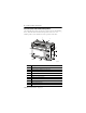
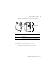
Foundation Fieldbus Linking Device Parts Illustration of the Fieldbus Linking Device The sample illustration shows the parts that comprise the 1757-FFLD linking device, which links Rockwell Automation products and FOUNDATION Fieldbus products on the Ethernet network to products on H1 links.
Foundation Fieldbus Linking Device 7 Before You Begin The following software is compatible with this revision of the linking device: • • • • RSFieldbus software, version 2.03 or later RSLogix 5000 programming software, version 16.03 or later RSLinx Classic software, version 2.52 or later Logix5000 Clock Update tool Install the Linking Device Install your linking device by using the instructions on the following pages.
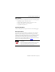
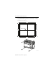
Foundation Fieldbus Linking Device Product Dimensions Dimension Measurement Height (A) 138 mm (5.43 in.) Width (B) 168 mm (6.62 in.) Depth (C) 87 mm (3.43 in.) A B C 43481 Mount on a DIN Rail The linking device DIN-rail latch locks in the open position so that the linking device can be easily attached to or removed from the DIN rail. The maximum extension of the latch is 15 mm (0.67 in.) in the open position. You need a screwdriver to remove the linking device.
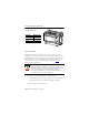
Foundation Fieldbus Linking Device 9 3. While pressing the linking device down against the top of the rail, snap the bottom of the linking device into position. Top Slot B Middle of DIN DIN Rail A C 43482 Dimension Height A 138 mm (5.43 in.) B 69 mm (2.715 in.) C 69 mm (2.715 in.) DIN latch closed, 76.1 mm (3 in.) DIN latch open Mount on a Panel Follow these steps to install your linking device on a panel. 1. Verify that the placement of the linking device allows for 50 mm (2 in.
Foundation Fieldbus Linking Device 2. Use the following figures to mount the linking device to a panel by using #8 or M4 screws tightened to 1.1…1.8 N•m (10…16 lb•in). All dimensions are in mm (in.). 168 (6.62) DIN Rail Center Line 132 (5.19) 122 (4.813) 147 (5.
Foundation Fieldbus Linking Device 11 Wire the Linking Device Wire your linking device by using these instructions. WARNING • If you connect or disconnect wiring while the field-side power is on, an electrical arc can occur. This could cause an explosion in hazardous location installations. Be sure that power is removed or the area is nonhazardous before proceeding. • When you change switch settings while power is on, an electrical arc can occur.
Foundation Fieldbus Linking Device Ethernet Connection WARNING If you connect or disconnect the communication cable with power applied to this module or any device on the network, an electrical arc can occur. This could cause an explosion in hazardous location installations. Be sure that power is removed or the area is nonhazardous before proceeding Connect your Ethernet cable to the Ethernet port on the underside of the linking device.
Foundation Fieldbus Linking Device 13 3. Complete step 1 and step 2 for all H1 cables. 4. Insert the RTB into the corresponding socket. H1 Terminal Block Layout (catalog number 1757-FFLD4 shown) + - + - + - + H1-1 + - + - + - + - H1-2 H1-3 H1-4 Power and Grounding IMPORTANT You must use a power conditioner between your fieldbus power supply and the devices on the fieldbus network. For more information, see the FOUNDATION Fieldbus specifications at http://www.fieldbus.
Foundation Fieldbus Linking Device Configure the Linking Device The following instructions describe how to configure and set up network parameters for your linking device. Assign an IP Address The Rockwell Automation BOOTP/DHCP Server (BOOTP) is a standalone program that combines the functionality of standard BOOTP software with DHCP software. The linking device is shipped with DHCP enabled. To configure the linking device by using BOOTP, perform the following steps. 1.
Foundation Fieldbus Linking Device 15 3. Double-click the request. A New Entry dialog box opens. 4. Type the IP address for the linking device. 5. Click OK. The device is added to the Relation List at the bottom of the BOOTP/DHCP Server window. 6. To permanently assign this configuration to the linking device, select the device and click Disable BOOTP/DHCP. When you cycle power to the linking device, it uses the configuration you assigned and does not issue a DHCP request.
Foundation Fieldbus Linking Device 7. To enable DHCP for the linking device, select the device and click Enable DHCP. Save the Relation List You can save the Relation List for later use. Do these steps to save the Relation List. 1. From the File menu, choose Save As. The Save dialog box opens. 2. Choose the location to save in. 3. Type a File name for the Relation List (for example, ‘Control System Configuration’) and click Save.
Foundation Fieldbus Linking Device 17 Set the Linking Device’s Network Parameters 1. Open RSLinx software and click the RSWho icon. 2. Browse to the linking device under the Ethernet/IP driver. 3. Right-click the linking device and choose Module Configuration to set network parameters.
Foundation Fieldbus Linking Device 4. Click the Port Configuration tab to view or change parameters. 5. When you finish making changes, click Apply and then OK. Troubleshoot the Linking Device The following instructions describe how to maintain your linking device. Reset the Linking Device You can reset the linking device with the: • reset jumper (locally). • reset button (locally). • web page (remotely). To use the reset jumper or reset button, follow the procedures below.
Foundation Fieldbus Linking Device 19 Reset Configuration The Reset Configuration removes power from the battery, clearing all downloaded fieldbus configurations. The linking device retains its network configuration and web page password information through this reset. Do these steps to reset configuration. 1. Remove power from the linking device. WARNING If you insert or remove the jumper while the power is on, an electrical arc can occur.
Foundation Fieldbus Linking Device Status Indicators Linking Device Status Indicators Indicator Status Description H1 Off The linking device H1 channel is inactive. Verify that the linking device is connected to the H1 network. Flashing green The linking device H1 channel is active. STATUS (module) Off No power - Module does not have 24V DC power. Verify that power is supplied to the module. Flashing green Standby - Module not configured.(1) Green Operational - Module operating correctly.
Foundation Fieldbus Linking Device 21 Linking Device Status Indicators Indicator Status Description MODE Solid green Linking device operational. Flashing green Linking device out-of-service. Verify that the Resource Block is set to Target Auto mode. (1) If you already set the IP address and the Status and Mode indicators are flashing green, you may have a duplicate IP address with another device on your network.
Foundation Fieldbus Linking Device 1757-FFLD2, 1757-FFLD4 - Technical Specifications Attribute Value Wiring category(2) 2 - on Fieldbus ports 3 - on power ports 2 - on Ethernet ports Terminal block torque specifications 0.34 N•m (3 lb•in) on power and Fieldbus wire connections Wire size DC power connection 0.2... 1.5 mm2 (26...16 AWG) solid or stranded copper wire rated at 75 °C (167 °F) or greater 1.2 mm (3/64 in.) insulation max Fieldbus connections 0.
Foundation Fieldbus Linking Device 23 1757-FFLD2, 1757-FFLD4 - Environmental Specifications Attribute Value Operating temperature 0…60 °C (32…140 °F) IEC 60068-2-1 (Test Ad, Operating Cold) IEC 60068-2-2 (Test Bd, Operating Dry Heat) IEC 60068-2-14 (Test Nb, Operating Thermal Shock) Nonoperating temperature -40…85 °C (-40…185 °F) IEC 60068-2-1 (Test Ab, Unpackaged Nonoperating Cold) IEC 60068-2-2 (Test Bb, Unpackaged Nonoperating Dry Heat) IEC 60068-2-14 (Test Na, Unpackaged Thermal Shock) Relative hu
Foundation Fieldbus Linking Device 1757-FFLD2, 1757-FFLD4 - Environmental Specifications Attribute Value Radiated RF immunity 1V/m with 1 kHz sine-wave 80% AM from 2000…2700 MHz IEC 61000-4-3 10V/m with 1 kHz sine-wave 80% AM from 80…2000 MHz 10V/m with 200 Hz 50% Pulse 100% AM at 900 MHz and 1890 MHz EFT/B immunity ±2 kV at 5 kHz on power ports IEC 61000-4-4 ±2 kV at 5 kHz on shielded Fieldbus ports ±2 kV at 5 kHz on Ethernet ports Surge transient immunity IEC 61000-4-5 ±2 kV line-earth (CM)
Foundation Fieldbus Linking Device 25 1757-FFLD2, 1757-FFLD4 - Certifications(1) Certification (2) Value CE European Union 2004/108/EC EMC Directive, compliant with: • EN 61326-1; Meas./Control/Lab.
Foundation Fieldbus Linking Device Additional Resources These documents contain additional information concerning related Rockwell Automation products. Resource Description FOUNDATION Fieldbus Wiring and Installation Application Guide publication at http://www.fieldbus.org, publication AG-140 Provides information on how to wire, power, and configure network components. FOUNDATION Fieldbus Intrinsic Safe Systems Application Guide at http://www.fieldbus.
Foundation Fieldbus Linking Device 27 Notes: Publication 1757-IN021E-EN-P - August 2009
Rockwell Automation Support Rockwell Automation provides technical information on the Web to assist you in using its products. At http://www.support.rockwellautomation.com you can find technical manuals, a knowledge base of FAQs, technical and application notes, sample code and links to software service packs, and a MySupport feature that you can customize to make the best use of these tools.