
Manual

24 Publication 1757-UM007D-EN-P - December 2008
Chapter 2 Configure the 1757-ABRIO Module
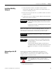
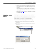
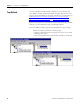
4. Select the slot location for the module.
To do this, you should be familiar with Allen-Bradley addresses
and, in particular, with 1771 addressing modes (see below).
See I/O Module Documentation
on page 84 for a list of related
ControlLogix documentation.
5. Click OK.
Addressing Modes for 1771
The 1771 chassis have three addressing modes - 1/2-slot, 1-slot and
2-slot addressing. The addressing mode is set by switches in the
backplane of the chassis and is set on a per-chassis basis. The
addressing mode determines how physical block transfer modules
map into logical addresses (rack, I/O group and slot).
In the following tables, the addresses used for modules in a 16-slot
rack in each addressing mode. The rack switches are set for rack 1,
starting I/O group 0.
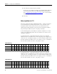
As illustrated in the 2-slot addressing table below, the controller
addresses two I/O module slots as one I/O group. For example, for a
chassis at rack 1, starting I/O group 0, a block transfer module in the
first slot would be at address rack 1, I/O group 0, slot 0. A module in
the next slot would be at rack 1, I/O group 0, slot 1.
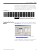
As illustrated in the 1-slot addressing table below, the controller
addresses one I/O module slot as one I/O group. For example, for a
chassis at rack 1, starting I/O group 0, a block transfer module in the
first slot would be at address rack 1, I/O group 0, slot 0. A module in
the next slot would be at rack 1, I/O group 1, slot 0.
2-Slot Addressing
Slot in chassis0123456789101112131415
Rack 1111111111111111
I/O Group 0011223344556677
Slot 0101010101010101
1-Slot Addressing
Slot in chassis0123456789101112131415
Rack 1111111122222222
I/O Group 0123456701234567
Slot 0000000000000000