Process Remote I/O (RIO) Communication Interface Module User Manual (Catalog Number 1757-ABRIO)
Important User Information Solid state equipment has operational characteristics differing from those of electromechanical equipment. Safety Guidelines for the Application, Installation and Maintenance of Solid State Controls (publication SGI-1.1 available from your local Rockwell Automation sales office or online at http://literature.rockwellautomation.com) describes some important differences between solid state equipment and hard-wired electromechanical devices.
Table of Contents Preface Purpose of this Manual . . . . . . . . . . . . . . . . . . . . . . . . . . . . . 7 Who Should Use this Manual. . . . . . . . . . . . . . . . . . . . . . . . . 7 Additional Resources. . . . . . . . . . . . . . . . . . . . . . . . . . . . . . . 7 Chapter 1 Introduction Introduction . . . . . . . . . . . . . . . . . . . . . . . . . . . . . . . . . . . . Process Remote I/O (RIO) Communication Interface Module RSLinx Software Requirements. . . . . . . . . . . . . . . . . . . . . . .
Table of Contents Chapter 3 Creating Generic Modules in AbRioCfg Software Introduction . . . . . . . . . . . . . . . . . . . . . . . . . . . . Generic Module Overview. . . . . . . . . . . . . . . . . . Generic Module Configuration File . . . . . . . . . . . Configuration Block Transfer Write. . . . . . . . . Data Block Transfer Read. . . . . . . . . . . . . . . . Data Block Transfer Write . . . . . . . . . . . . . . . Creating a Generic Module in AbRioCfg software . . . . . . . . . . . . . . . . . . .
Table of Contents Chapter 7 Monitoring the 1757-ABRIO Module Introduction . . . . . . . . . . . . . . . . . . . . . . Monitoring the Operation . . . . . . . . . . . . Monitoring Digital I/O. . . . . . . . . . . . . . . Monitoring the Data Value of Tags. . . . . . Monitoring the Status of a Block Transfer. Monitoring the Scanner Log. . . . . . . . . . . Monitoring Diagnostic Counters. . . . . . . . Active Rack List . . . . . . . . . . . . . . . . . Global Diagnostic Counters . . . . . . . . Fatal Errors .
Table of Contents 1771-NIV Module . . . . . . Module Configuration I/O Data . . . . . . . . . . Diagnostic Data . . . . . 1771-NR Module . . . . . . . Module Configuration I/O Data . . . . . . . . . . Diagnostic Data . . . . . . . . . . . . . . . . . . . . . . . . . . . . . . . . . . . . . . . . . . . . . . . . . . . . . . . . . . . . . . . . . . . . . . . . . . . . . . . . . . . . . . . . . . . . . . . . . . . . . . . . . . . . . . . . . . . . . . . . . . . . . . . . . . . . . . . . . . .
Table of Contents Appendix C Operational Comparison Between Normal Operational Messages . . . . . . . . . . . . . . . . . . . . . . Exception Handling Messages . . . . . . . . . . . . . . . . . . . . . . the 1757-ABRIO Module and a PLC-5 System Appendix D Tag Descriptions for Scheduled Configuration Tag . . . . . . . . . . . . . . . . . . . . . . . . . . . . I and O Tags . . . . . . . . . . . . . . . . . . . . . . . . . . . . . . . . Data in RSLogix 5000 Software 143 145 149 149 Status Tag . . . . . . .
Table of Contents 8 Publication 1757-UM007D-EN-P - December 2008
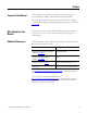
Preface Purpose of this Manual This manual describes how to configure and troubleshoot your Process Remote I/O (RIO) Communication Interface Module. For installation information, refer to the Process Remote I/O (RIO) Communication Interface Module Installation Instructions, publication 1757-IN916. Who Should Use this Manual We assume you have a good understanding of Remote I/O (RIO) modules as well as the host controller system (ProcessLogix or ControlLogix).
Table of Contents 8 Preface Publication 1757-UM007D-EN-P - December 2008
Chapter 1 Introduction Introduction This chapter: describes the 1757-ABRIO Remote I/O Module. lists the RSLinx software requirements. provides update procedures for the module’s firmware. Process Remote I/O (RIO) Communication Interface Module This document is a user guide for the 1757-ABRIO module, which lets Rockwell Automation controllers (ProcessLogix or ControlLogix) communicate with Allen-Bradley remote I/O. The module acts as a RIO network scanner.
Chapter 1 Introduction As an RIO network scanner, the module: scans 1771 racks with rack numbers from 1 to 37 octal. supports baud rates of 57.6, 115.2 and 230.4 kilobaud. supports up to 32 adapters with any mix of full/partial racks. automatically manages and performs block transfers, update time can be defined for each block transfer. provides full diagnostic counters for alarms and maintenance. automatically performs scaling of raw analog data.
Introduction ProcessLogix System Quick Start Chapter 1 Use the following steps to quickly get the module running in a ProcessLogix system. Detailed information about each step is available in other sections of this manual or in the installation manual. You can only have one scanner per RIO network. Remove any other scanners on the RIO network before continuing. 1. Install the 1757-ABRIO module in the chassis and connect it to the RIO network.
Chapter 1 Introduction RSLogix 5000 System Quick Start Use the following steps to quickly get the module running in an RSLogix 5000 system. Detailed information about each step is available in other sections of this manual or in the installation manual. You can only have one scanner per RIO network. Remove any other scanners on the RIO network before continuing. 1. Install the 1757-ABRIO module in the chassis and connect it to the RIO network.
Introduction Chapter 1 9. If you are using: a. a scheduled network, establish an Exclusive Owner or Input Only connection from the ControlLogix controller to access digital data within the 1757-ABRIO module. See Setup an Exclusive-owner Connection on page 60 or Setup Input-only Connections on page 63. b. an unscheduled network, configure tags and ladder logic in RSLogix 5000 software to access information within the 1757-ABRIO module. See Unscheduled I/O Connections in ControlLogix on page 67.
Chapter 1 Introduction Update the 1757-ABRIO Module’s Firmware The 1757-ABRIO module supports firmware upgrades using ControlFLASH or NTools software. The firmware version is displayed on the 1757-ABRIO module’s 4-character display when you power up the module. For ProcessLogix software users, if your 1757-ABRIO module revision is: at or less than 1.2, use ControlFlash software to update the module firmware. greater than 1.2, use NTools software to update the module firmware.
Introduction Chapter 1 10. Click 1757-ABRIO and click Next. 11. Expand the RSLinx Tree window to the location of the 1757-ABRIO module you wish to flash. 12. Select the module icon and click OK. 13. Confirm new revision for this update and click Next. 14. At the Summary window, click Finish. 15. To confirm the flash, click Yes. 16. Click OK. If this update is successful, the Update Status window displays the following message in green: Update Complete.
Chapter 1 Introduction 8. Click the firmware button and click Yes to acknowledge the warning. 9. Navigate to: D:(or your CD-ROM drive letter)\Firmware_NTools 10. Select the appropriate .nvs file. 11. To start the firmware load, click Open. 12. To confirm, click Yes. The Status field in the lower portion of the Network Tools window tracks the load progress. 13. When the load completes, click OK.
Chapter 2 Configure the 1757-ABRIO Module Introduction This chapter: provides an overview of the AbRioCfg software. gives an introduction to mapping and accessing RIO network data. explains how to install the AbRioCfg software. explains how to autoconfigure I/O racks. explains how to add and configure block transfer modules. AbRioCfg Software Overview The 1757-ABRIO module ships with configuration software, called AbRioCfg. This configuration software is an online configuration tool.
Chapter 2 Configure the 1757-ABRIO Module Mapping and Accessing RIO Network Data Use the provided AbRioCfg software to create tags which are arrays of digital, floating point or text values that the host controller reads or writes using unscheduled messages. You map data that the module receives or sends into these tags. The data mapping is stored in flash memory on the 1757-ABRIO module.
Configure the 1757-ABRIO Module Installing AbRioCfg Software Chapter 2 1. Verify that RSLinx software and RSLinx OEM or RSLinx Professional (not RSLinx Lite) software is installed before you install the AbRioCfg software. 2. Insert the CD supplied with the 1757-ABRIO module and run the program setup.exe. 3. Confirm that you have RSLinx OEM or RSLinx Professional (not RSLinx Lite) software installed. IMPORTANT Messages about the DTL32.
Chapter 2 Configure the 1757-ABRIO Module 2. Click Hardware Config to highlight it and activate the AbRioCfg menu toolbar. TIP With AbRioCfg software, 2.0 and higher, you can also manually configure the I/O racks in your network. Refer to Add Racks Offline on page 33 for more information. 3. Click the Autoconfig button in the toolbar. An RSWho window opens.
Configure the 1757-ABRIO Module Chapter 2 4. Navigate to the 1757-ABRIO module. 5. Select the module and click OK. The Select Baud Rate dialog box opens. 6. Select the appropriate baud rate and click OK. The baud rate in this example is set by switches on the 1771-ASB adapter. See your device documentation for how to set the desired baud rate. All racks or devices on one RIO network must operate at the same baud rate.
Chapter 2 Configure the 1757-ABRIO Module The 1757-ABRIO module sends messages to all possible racks and builds the network rack configuration from the responses. It displays a list of the racks it found in the network tree. If you expand a rack, the partial racks that make up that rack number are displayed. 7. If you are using 1771 remote I/O modules, a. Right-click the rack in the network tree and select Enter Rack Switch Setting. The Select Rack Setting dialog box opens.
Configure the 1757-ABRIO Module Chapter 2 b. Select the value that matches the Last State switch setting in the backplane of the I/O chassis, either De-energize or Hold Last State. This setting tells the 1757-ABRIO module what to do if the controller stops updating the tag to which this chassis’s digital data is mapped. c. Repeat steps 7a and 7b for all racks that contain 1771 remote I/O modules.
Chapter 2 Configure the 1757-ABRIO Module 4. Select the slot location for the module. To do this, you should be familiar with Allen-Bradley addresses and, in particular, with 1771 addressing modes (see below). See I/O Module Documentation on page 84 for a list of related ControlLogix documentation. 5. Click OK. Addressing Modes for 1771 The 1771 chassis have three addressing modes - 1/2-slot, 1-slot and 2-slot addressing.
Configure the 1757-ABRIO Module Chapter 2 As illustrated in the 1/2-slot addressing table below, the controller addresses 1/2 of an I/O module slot as one I/O group. For example, for a chassis at rack 1, starting I/O group 0, a block transfer module in the first slot would be at address rack 1, I/O group 0, slot 0. A module in the next slot would be at rack 1, I/O group 2, slot 0.
Chapter 2 Scaling Configure the 1757-ABRIO Module Part of the configuration procedure for analog modules is entering scaling values. The 1757-ABRIO module performs scaling between raw I/O data and floating point user values. You can send floating point output values to the 1757-ABRIO module which it converts to raw output values using the scaling values you supplied in the configuration. Similarly, the 1757-ABRIO module converts raw input data to floating point values, using the scaling you enter.
Configure the 1757-ABRIO Module Chapter 2 Output Scaling For output modules, you supply the floating point values you want to correspond to the minimum and maximum raw output values. ATTENTION The minimum scale value may not be larger than the maximum scale value EXAMPLE If a channel has a range of 1 5 V dc and you set the minimum scaling value to 12.3 and the maximum scaling value to 77.4, when you set the output value to 12.3, the module produces a raw output value of 1 V dc.
Chapter 2 Configure the 1757-ABRIO Module Tags Defined The ProcessLogix or ControlLogix controller accesses data for the 1757-ABRIO module using unscheduled messages that read or write tags. For more information on how the controllers access this data, see Configuring the ProcessLogix Controller to Access Data on the 1757-ABRIO Module on page 51 and Configuring RSLogix 5000 Software to Access Data on the 1757-ABRIO Module on page 57.
Configure the 1757-ABRIO Module Chapter 2 Flag Read (3) and Flag Write (4) tags – Flag read and write tags are arrays of 512 bits. – Block transfer modules also have status bits that can be mapped to flag read tags. – Dragging an entire I/O Grp to a Flag Read or Flag Write tag will expose all discrete read or write values for that rack as well as the Rack Global Status tag. Text Read (5) tags – Text read tags are arrays of 64 bytes. – They are used only with the 1770-HT1 HART module.
Chapter 2 Configure the 1757-ABRIO Module Create a Tag If you are planning to use automatic digital tags via a scheduled connection to the 1757-ABRIO module from a ControlLogix controller, do not create tags. Refer to Scheduled Digital I/O Connections in RSLogix 5000 Programs on page 60. For all other tag types (analog, text) and unscheduled connections, tags must be manually created. To create a tag, complete the following steps. 1. Select the appropriate tab for the type of tag you want to create. 2.
Configure the 1757-ABRIO Module Mapping Data to Tags in AbRioCfg Software Chapter 2 If you are using a ControlLogix controller, no actions are necessary to read or write digital data with scheduled connections. Refer to Scheduled Digital I/O Connections in RSLogix 5000 Programs on page 60 for more information. TIP Rack Digital Data If you would like to use scheduled ControlNet connections to the 1757-ABRIO module via a ControlLogix controller, do not map any racks to digital tags.
Chapter 2 Configure the 1757-ABRIO Module I/O To map I/O data to a tag, complete the following steps. 1. Expand the tag to show the tag elements. 2. Scroll to display the destination in the tag where you want to add the data. 3. Drag the rack or block transfer module to the desired location in the tag. Deleting Mapped Data To delete mapped data from a tag, complete the following steps. 1. Select any element of the data. 2. Click Delete. You cannot delete individual elements of the data for an I/O module.
Configure the 1757-ABRIO Module Chapter 2 Add Racks Offline To add a rack, complete the following steps. 1. Right-click Hardware Config and select Add A Rack. 2. Enter the Rack Number (1 to 37 octal), Starting I/O Group (0,2,4,6) and Ending I/O Group (1,3,5,7) and click OK.
Chapter 2 Configure the 1757-ABRIO Module Delete Racks Offline To delete racks offline, complete the following steps. 1. Right-click the partial rack and select Delete Rack. A warning dialog box opens. 2. Click OK. When you delete a rack, all I/O modules on the rack and flag mappings for the rack are deleted. If this partial rack is the only one in the rack number, the rack number will be deleted from the tree.
Configure the 1757-ABRIO Module Chapter 2 Change the Baud Rate Offline To change the baud rate offline, complete the following steps. 1. Select Actions>Change Baud Rate. The Select Baud Rate dialog box opens. 2. Select the desired baud rate and click OK. A warning window opens 3. To select the path to the 1757-ABRIO module from an RSWho window, click Yes. To make this change in the offline file only, click No.
Chapter 2 Configure the 1757-ABRIO Module Upload the Configuration 36 To upload a configuration from a 1757-ABRIO module, select Actions>Upload config or click the Upload Config From Module button on the toolbar.
Chapter 3 Creating Generic Modules in AbRioCfg Software Introduction This chapter describes using a generic module type which supports any block transfer I/O module that uses 16-bit integer data. To use these features, you need the following: Firmware version 2.1 or above of the firmware for the 1757-ABRIO module AbRioCfg software version 2.1 or above AbRioCfg software version 2.1 or above can open or upload configurations made with previous versions of AbRioCfg software.
Chapter 3 Creating Generic Modules in AbRioCfg Software Generic Module Configuration File The Generic Module configuration file consists of these sections. – the configuration block transfer write (BTW) – the data block transfer read – the data block transfer write Most configuration files have a configuration block transfer write. Some may have both data block transfer read and data block transfer write sections; others will have just one or the other.
Creating Generic Modules in AbRioCfg Software Chapter 3 The offset is the offset into the block transfer and ranges from 0 to the block transfer length - 1. For example, if the block transfer is 10 words long, the allowed offsets range from 0 to 9. The value can be in one of the following formats: Format Range Binary 0b0000000000000000 to 0b1111111111111111 Hexadecimal 0x0000 to 0xFFFF Unsigned integer 0 to 65535 Signed integer -32768 to 32767 Binary values start with a leading “0b”.
Chapter 3 Creating Generic Modules in AbRioCfg Software Example: 1771-IFE Module The following configuration block transfer write file configures a 1771-IFE for the following: differential operation (8 input channels) each channel set for 1-5 VDC or 4-20 mA two's complement binary data format each channel's raw data scaled between 0 and 4095 configbtw, 21 ; length 21 0, 0 1, 0 2, 0x0500 ; differential inputs, binary 3, 0 4, 0 5, 0 6, 0x4095 ; channel 1 scaling 7, 0 8, 0x4095 ; channel 2 scaling 9, 0 10, 0
Creating Generic Modules in AbRioCfg Software Chapter 3 Example: 1771-OFE module The following configuration block transfer write file configures a 1771-OFE for: binary data format raw data from 0 to 0x0fff (0 to 4095 decimal) on each channel configbtw, 13 ; length 13 4, 0x8000 ; binary data format 6, 0x0fff ; maximum raw value channel 8, 0x0fff ; maximum raw value channel 10, 0x0fff ; maximum raw value channel 12, 0x0fff ; maximum raw value channel 1 2 3 4 0 values have been omitted.
Chapter 3 Creating Generic Modules in AbRioCfg Software AbRioCfg software checks the number of values to be defined against the actual number of definitions and indicates an error if they do not match. The format can be one of: Format Range of values BCD 0 to 9999 Unsigned 0 to 65535 Integer -32768 to 32767 All items must have the same format.
Creating Generic Modules in AbRioCfg Software Chapter 3 If the module does not have overrange or underrange bits, leave those fields blank in the configuration file. Some modules have a separate polarity bit to indicate the sign of an input. If the polarity bit is set, the 1757-ABRIO module assigns the corresponding data a negative value. the 1757-ABRIO module uses the polarity offset and bit only for the BCD data type. It ignores them for the other data types.
Chapter 3 Creating Generic Modules in AbRioCfg Software The offset is an offset into the block transfer. It can range from 0 to the length of the block transfer - 1. If the offset is followed by an “H”, it refers to the high byte of the block transfer word. The length can range from 8 to 504 and must be a multiple of 8. The sum of the lengths in the data definitions must match the length in the “flag” line.
Creating Generic Modules in AbRioCfg Software Chapter 3 Sample 1771-IFE Configuration File configbtw, 21 ; length 21 2, 0x0500 ; differential inputs, binary 5, 0 6, 0x4095 ; channel 1 scaling 7, 0 8, 0x4095 ; channel 2 scaling 9, 0 10, 0x4095 ; channel 3 scaling 11, 0 12, 0x4095 ; channel 4 scaling 13, 0 14, 0x4095 ; channel 5 scaling 15, 0 16, 0x4095 ; channel 6 scaling 17, 0 18, 0x4095 ; channel 7 scaling 19, 0 20, 0x4095 ; channel 8 scaling databtr, 12 numeric, 4, signed 4, 1, 0, 2, 0, 3, 0, 0, 4095, 0
Chapter 3 Creating Generic Modules in AbRioCfg Software Numeric Data The numeric section of the data block transfer write defines the I/O data - its location, format, and scaling. The beginning of the numeric section is marked by the keyword “numeric”, the number of values to be defined, and the data format. AbRioCfg software checks the number of values to be defined against the actual number of definitions and indicates an error if they do not match. The format can be one of the following.
Creating Generic Modules in AbRioCfg Software Chapter 3 The 1757-ABRIO module uses the polarity offset and bit only for the BCD data type. It ignores them for the other data types. TIP If the data type is BCD, enter the raw minimum and maximum values in decimal, not hexadecimal. For example is the range is 0 to 9999, enter the value as 9999, not 0x9999. If the scaled valued written is NaN, the raw output gets set to the corresponding value in the configuration data.
Chapter 3 Creating Generic Modules in AbRioCfg Software The sum of the lengths in the data definitions must match the length in the “flag” line.
Creating Generic Modules in AbRioCfg Software Chapter 3 2. Select a Module Type of Generic Module, the location for the module and click OK. 3. Browse to or type the CSV file and path and click Import. AbRioCfg software imports the configuration file and displays the contents, or gives an error message if it finds problems with the file. 4. Assign values for the BTR and BTW Update Times. 5. Click OK to accept the module.
Chapter 3 Creating Generic Modules in AbRioCfg Software You can export the generic module configuration by clicking the Export button in the Generic Module dialog box. Since comments in the original file are not imported (and therefore are not exported), it is usually better to modify the original configuration file and save it with a new name. Export may be useful if you upload a configuration that contains a generic module from a 1757-ABRIO module and you do not have the original file.
Chapter 4 Configuring the ProcessLogix Controller to Access Data on the 1757-ABRIO Module Introduction This chapter describes: the operating modes of the 1757-ABRIO module. how to access data on the module from a ProcessLogix controller. Modes of Operation There are four modes of operation for the module. CONFIG INACTIVE (Program) ACTIVE (Run) FORCED ACTIVE The mode of the 1757-ABRIO module determines the RIO network mode.
Chapter 4 Configuring the ProcessLogix Controller to Access Data on the 1757-ABRIO Module INACTIVE Mode The module is in INACTIVE mode when it is not receiving messages from either a host controller or via OPC/DDE. The module is also in INACTIVE mode when it has not been put in FORCED ACTIVE mode by AbRioCfg software. When the module is in INACTIVE mode, the RIO network is placed in program mode with input updates but no output updates.
Configuring the ProcessLogix Controller to Access Data on the 1757-ABRIO Module Configure the 1757-PLX52 Controller Chapter 4 To access tag data on the 1757-ABRIO module from a ProcessLogix controller, use the REQNUMARRAY, REQFLAGARRAY and REQTEXTARRAY Exchange Blocks with CIPREAD and CIPWRITE commands to read and write tags. Use Control Builder software to complete the following steps. 1. Select the Exchange Block from the Library in Control Builder. 2.
Chapter 4 Configuring the ProcessLogix Controller to Access Data on the 1757-ABRIO Module 7. Set the number of values to be read or written. a. Flag arrays, 512 max b. Numeric arrays, 64 max c. Text arrays, 64 max Array Examples Flag Arrays Numeric Arrays Text Arrays 8. Set the data type to be read or written. a. Numeric arrays, set Data Type in Target Device to FLOAT32. b. Text arrays, set the Number of String Values to 1 and the Char Length of String Values to 64. 9. Select the Communications tab.
Configuring the ProcessLogix Controller to Access Data on the 1757-ABRIO Module Chapter 4 11. Set the File Name in the Exchange Blocks to the names of the tags you created in the 1757-ABRIO module. 12. Perform any other configuration required by your application on the other tabs. IMPORTANT Be sure to expose the Error codes in your Exchange Blocks. 13. Click OK to accept the block. 14. Wire the ready flag (READYFL) to the send flag (SENDFL) for each exchange block. 15.
Chapter 4 Configuring the ProcessLogix Controller to Access Data on the 1757-ABRIO Module Live Data Examples Double-click function block 56 Publication 1757-UM007D-EN-P - December 2008
Chapter 5 Configuring RSLogix 5000 Software to Access Data on the 1757-ABRIO Module Introduction This chapter describes: the operating modes of the 1757-ABRIO module. how to access data on the module from a ControlLogix controller. Modes of Operation There are four modes of operation for the module. CONFIG INACTIVE (Program) ACTIVE (Run) FORCED ACTIVE The mode of the 1757-ABRIO module determines the RIO network mode.
Chapter 5 Configuring RSLogix 5000 Software to Access Data on the 1757-ABRIO Module INACTIVE Mode The module is in INACTIVE mode when it is not receiving messages from either a host controller or via OPC/DDE. The module is also in INACTIVE mode when it has not been put in FORCED ACTIVE mode by AbRioCfg software. When the module is in INACTIVE mode, the RIO network is placed in program mode with input updates but no output updates. The 1757-ABRIO module must be in the INACTIVE mode to accept a download.
Configuring RSLogix 5000 Software to Access Data on the 1757-ABRIO Module Chapter 5 FORCED ACTIVE Mode The module is in FORCED ACTIVE mode when you set ACTIVE mode from the AbRioCfg program. FORCED ACTIVE mode lets you send and receive data without having to create messages in the module. It is intended primarily for setting up and testing RIO networks. If you try to download a configuration when the module is in FORCED ACTIVE mode, AbRioCfg software asks if you want to take the module out of ACTIVE mode.
Chapter 5 Configuring RSLogix 5000 Software to Access Data on the 1757-ABRIO Module Scheduled Digital I/O Connections in RSLogix 5000 Programs 1757-ABRIO module firmware versions 1.2 and above support scheduled connections for exchanging digital input and output data between the 1757-ABRIO module and the host ControlLogix controller. This results in much faster updates for the digital data than is possible using unscheduled messages.
Configuring RSLogix 5000 Software to Access Data on the 1757-ABRIO Module Chapter 5 Remote I/O Operating Modes If there is an exclusive-owner connection to the 1757-ABRIO module, the module’s remote I/O mode (run or program) follows the owner ControlLogix controller’s Run or Program mode. If the owner ControlLogix controller is in Program mode, the 1757-ABRIO module is in program mode (even if the module is receiving messages).
Chapter 5 Configuring RSLogix 5000 Software to Access Data on the 1757-ABRIO Module 6. Type a Name and a Description for the module, if desired. 7. Set the Slot number for the module in the ControlLogix chassis. 8. For the Comm Format, select Data - INT - With Status. 9. Select the following values for the Connection Parameters. Assembly Instance Size Input 1 250 Output 2 248 Configuration 4 0 Status Input 5 10 Status Output 6 N/A 10.
Configuring RSLogix 5000 Software to Access Data on the 1757-ABRIO Module Chapter 5 Output Priority If a digital rack is mapped to a flag write tag in the AbRioCfg software, the flag data takes precedence over the digital outputs in the scheduled connection, even if nothing is writing to the flag write tag. To control outputs on a chassis using a scheduled connection, make sure the chassis is not mapped to a flag write tag.
Chapter 5 Configuring RSLogix 5000 Software to Access Data on the 1757-ABRIO Module The Module Properties dialog box opens. 6. Type a Name and a Description for the module, if desired. 7. Set the Slot number for the module in the ControlLogix chassis. 8. For the Comm Format, select Input Data - INT - With Status. 9. Select the following values for the Connection Parameters.
Configuring RSLogix 5000 Software to Access Data on the 1757-ABRIO Module Chapter 5 10. Verify that the Open Module Properties checkbox is checked and click OK. 11. Set the module’s Requested Packet Interval. This is how often the module's scheduled data is updated in the controller. The value can range from 0.2 to 750 ms. The default is 5 ms.
Chapter 5 Configuring RSLogix 5000 Software to Access Data on the 1757-ABRIO Module 12. Click OK. 13. Save the program and download it to the ControlLogix controller. Click the 1757-ABRIO module to display the new tags. See Tag Descriptions for Scheduled Data in RSLogix 5000 Software on page 149 for details.
Configuring RSLogix 5000 Software to Access Data on the 1757-ABRIO Module Unscheduled I/O Connections in ControlLogix Chapter 5 There are several tasks you need to complete before you can access data from ControlLogix. You need to create the following: Tags for messages Tags for storage areas Message commands to read RIO network data Message commands to write RIO network data Use RSLogix 5000 message instructions (MSG) to access tags on the 1757-ABRIO module.
Chapter 5 Configuring RSLogix 5000 Software to Access Data on the 1757-ABRIO Module 2. Create Message Commands to Read and Write All RIO Network Data RSLogix 5000 Example Message Commands in Program Mode Use the Browse button ( ) to locate the read/write tags you want to reference in your message commands. See Create a Tag on page 30 for more information. This table shows the source (write) or destination (read) data type to use with each 1757-ABRIO tag type and the size for each type.
Configuring RSLogix 5000 Software to Access Data on the 1757-ABRIO Module Chapter 5 Use the following steps to add the MSG instruction. WARNING The EN_CC bit in a ControlLogix MESSAGE tag defaults to on. If the message executes successfully even once, it gets retried periodically, even if the ladder logic has disabled the message. If you want to keep the connection open no matter what, turn on the bit.
Chapter 5 Configuring RSLogix 5000 Software to Access Data on the 1757-ABRIO Module 4. Select the Source Element. If you are writing to the 1757-ABRIO module, this is the ControlLogix controller tag. If you are reading from the 1757-ABRIO module, this is the name of the tag in the 1757-ABRIO module. TIP Use this tag To All_Analog_Read Read data from input modules. The tag is listed under Numeric Read Tags. All_Flag_Read[100] Flag read for status and digital data.
Configuring RSLogix 5000 Software to Access Data on the 1757-ABRIO Module Chapter 5 7. Select the Communication tab. 8. Type the path from the ControlLogix controller to the 1757-ABRIO module.
Chapter 5 Configuring RSLogix 5000 Software to Access Data on the 1757-ABRIO Module When you are using scheduled connections in ControlLogix this is automatically populated with your 1757-ABRIO module’s name and address through an RSNetworx network polling. TIP The 1757-ABRIO module, ProcessLogix controller and ControlLogix controller (most likely) will not be in the same racks.
Configuring RSLogix 5000 Software to Access Data on the 1757-ABRIO Module Chapter 5 Live Data Example Publication 1757-UM007D-EN-P - December 2008 73
Chapter 5 Configuring RSLogix 5000 Software to Access Data on the 1757-ABRIO Module Ladder Rung Example 74 Publication 1757-UM007D-EN-P - December 2008
Chapter 6 Accessing Data through a DDE or OPC Server Introduction This chapter describes how to access data on the module using a DDE or OPC Server. Accessing Data from a DDE or OPC Server You can access data on the 1757-ABRIO module directly using a DDE or OPC server such as RSLinx software, without the intervention of a host controller. Configuring a Topic in RSLinx Software Use the following procedure to use RSLinx software as a DDE or OPC server to access data on the 1757-ABRIO module. 1.
Chapter 6 Accessing Data through a DDE or OPC Server 12. Change Local or Remote Addressing defaults to Local. If you are using a bridge device to communicate with the 1757-ABRIO module, select Remote and configure the bridging. Refer to the RSLinx software documentation for detailed information on how to configure bridging. 13. Click Done to accept the DDE/OPC topic. Accessing the Data 1. Start your DDE or OPC client. 2. Connect to RSLinx software. The 1757-ABRIO module supports browsing of tags. 3.
Chapter 7 Monitoring the 1757-ABRIO Module Introduction This chapter provides the following information on: monitoring the operation of the 1757-ABRIO module. monitoring the data value of tags. monitoring the status of a block transfer. monitoring the scanner log. recognizing and clearing fatal errors. Monitoring the Operation The AbRioCfg software lets you monitor the operation of the module and perform maintenance operations.
Chapter 7 Monitoring the 1757-ABRIO Module Use the Edit>Write toolbar button or the menu item to enable editing. You can now change any data and it will be written to the network (outputs) or to the data table (inputs). However if the same data is being updated by I/O modules or the controller, the value you write is overwritten the next time this I/O module is scanned. Monitoring the Data Value of Tags To monitor the current data value in a tag, complete the following steps. 1.
Monitoring the 1757-ABRIO Module Chapter 7 If you attempt to monitor a tag that has not been downloaded to the 1757-ABRIO module, AbRioCfg software displays a message that indicates there is a configuration mismatch between the configuration in AbRioCfg software and the configuration in the 1757-ABRIO module. TIP Monitoring the Status of a Block Transfer Use the same procedure to monitor digital and text data. To monitor the current status of a block transfer, complete the following steps. 1.
Chapter 7 Monitoring the 1757-ABRIO Module Block Transfer Read Diagnostics Counter Description Ignored Req Running count of update requests ignored by the block transfer module. Prot Errors Running count of protocol errors for this block transfer read. If this counter is incrementing, the module isn't responding correctly. Possible causes are length mismatch, invalid reply. Request Count Count of the number of times on successive scans this block transfer was requested.
Monitoring the 1757-ABRIO Module Monitoring Diagnostic Counters Chapter 7 The 1757-ABRIO module maintains diagnostic counters that indicate the state of communication on the entire RIO network, as well as counters related to each chassis. It also maintains an active rack list. To monitor the diagnostic counters, select Tools>Monitor Diagnostic Counters or click the Start the Diagnostics Counters Monitor button. Active Rack List The active rack list shows where the racks are located.
Chapter 7 Monitoring the 1757-ABRIO Module The rack diagnostic counters consist of the following counters for each partial rack. Rack Diagnostic Counters Fatal Errors Counter Description Rx This counter increments when the 1757-ABRIO module receives a packet from this rack. Crc This counter increments when the 1757-ABRIO module receives a packet with a bad CRC from this rack.
Chapter 8 Supported 1771 Modules Introduction This chapter: lists the supported 1771 modules. describes module configuration, I/O Data, and diagnostic data. Module Description The 1757-ABRIO module supports all digital 1771 modules and the following 1771 block transfer modules. For information on how to communicate with other block transfer I/O modules, see Creating Generic Modules in AbRioCfg Software on page 37.
Chapter 8 Supported 1771 Modules Refer to the following publications for information on installing and using the supported modules. I/O Module Documentation 1771-IFE Module Module Installation Instructions User Manual 1771-ASB NA 1771-UM001 1771-IFE 1771-5.45 1771-6.5.90 1771-6.5.115 1771-OFE 1771-IN044 1771-6.5.30 1771-IR 1771-5.63 1771-6.5.76 1771-IXE 1771-5.64 1771-6.5.130 1771-IL 1771-5.62 1771-6.5.
Supported 1771 Modules Chapter 8 Module Configuration Configuring the 1771-IFE module consists of setting the following: single-ended or differential operation range and scaling for each channel digital filter and time constant real time sampling and time constant module update time When you add a 1771-IFE module to a rack, the 1771-IFE Module dialog box opens.
Chapter 8 Supported 1771 Modules To configure the 1771-IFE module, complete the following steps. 1. Set the Input Type to single-ended or differential operation. 2. For each channel select the voltage or current range and enter the scaling values. The low scaling value corresponds to the minimum input voltage or current; the high scaling value corresponds to the maximum voltage or current. For example, if the scaling values are 10.0 and 22.
Supported 1771 Modules Chapter 8 I/O Data The 1771-IFE module returns the 8 or 16 words of floating point data to the host controller, depending on whether the module is configured for single-ended or differential operation.
Chapter 8 Supported 1771 Modules IFE Diagnostic Data Bit Description 12 Channel 5 underrange 13 Channel 6 underrange 14 Channel 7 underrange 15 Channel 8 underrange 16 Channel 9 underrange 17 Channel 10 underrange 18 Channel 11 underrange 19 Channel 12 underrange 20 Channel 13 underrange 21 Channel 14 underrange 22 Channel 15 underrange 23 Channel 16 underrange 24 Channel 1 overrange 25 Channel 2 overrange 26 Channel 3 overrange 27 Channel 4 overrange 28 Channel 5 overra
Supported 1771 Modules 1771-OFE Module Chapter 8 The 1771-OFE module is a four-channel analog output module. The module is available in three different types. The 1771-OFE1 module has jumper-selectable voltage ranges. The 1771-OFE2 module is a 4 to 20 mA current module. The 1771-OFE3 module is a 0 to 50 mA current module. The 1771-OFE1 module supports ranges of 1 to 5V dc, 0 to 10V dc and -10 to 10V dc. Module Configuration When you add a 1771-OFE module to a rack, the 1771-OFE Module dialog box opens.
Chapter 8 Supported 1771 Modules 2. For each channel select the range for each channel and enter the scaling values. The low scaling value corresponds to the minimum output voltage or current; the high scaling value corresponds to the maximum output voltage or current. EXAMPLE If the scaling values are 10.0 and 22.5 and the range is configured for 0 to 5V dc, a value of 10.0 produces an output of 0V dc and a value of 22.5 produces an output of 5V dc. The range of scaling values is -3.4e38 to 3.4e38.
Supported 1771 Modules Chapter 8 Diagnostic Data The 1771-OFE module has 8 bits of diagnostic data that can be mapped to a flag read tag. OFE Diagnostic Data Bit Description 0 OFE good communication bit 1 reserved 2 reserved 3 reserved 4 Channel 1 data invalid bit 5 Channel 2 data invalid bit 6 Channel 3 data invalid bit 7 Channel 4 data invalid bit The good communication bit is set if the 1757-ABRIO module is successfully communicating with the 1771-OFE module.
Chapter 8 Supported 1771 Modules 1771-IR Module The 1771-IR module is a 6-channel RTD module. Supported RTDs include 100-ohm platinum and 10-ohm copper. You can use any other type but the results are returned in ohms. Module Configuration When you add a 1771-IR module to a rack, the 1771-IR Module dialog box displays.
Supported 1771 Modules Chapter 8 To configure the 1771-IR module, complete the following steps. 1. Set the global RTD type to either 10-ohm copper or 100-ohm platinum. If the RTD you are using is neither of these two, you will override each channel to report the results in ohms. 2. If the RTD type is set to 10-ohm copper, enter the resistance value at 25 C. 3. Select the Units of measurement, either degrees Fahrenheit or Celsius, or Ohms. 4.
Chapter 8 Supported 1771 Modules I/O Data The 1771-IR module returns 6 words of floating point data to the host controller. 1771-IR Module I/O Data Data Word Description 0 Channel 1 data 1 Channel 2 data 2 Channel 3 data 3 Channel 4 data 4 Channel 5 data 5 Channel 6 data This data is mapped to a numeric read tag. Diagnostic Data The 1771-IR module returns 16 bits of diagnostic data to the host controller.
Supported 1771 Modules 1771-IXE Module Chapter 8 The 1771-IXE module is an 8-channel thermocouple input module. The channels are configured in groups of four. The module supports types E, J, K, T, R and S thermocouples. The module can also be used as a millivolt input module. The range is from -100 to 100 mV. Module Configuration When you add a 1771-IXE module to a rack, the 1771-IXE Module dialog box displays. To configure the 1771-IXE module, complete the following steps. 1.
Chapter 8 Supported 1771 Modules 3. Set the gain and offset for each channel. See the Thermocouple/Millivolt Input Module User Manual, publication 1771-6.5.130, for more information. 4. If desired, enable real-time sampling (RTS) and set the sampling rate, from 0.1 to 3.1 seconds. This becomes the effective data update rate and may override the update rate if the update rate is smaller. 5. Set the Update Time for the module’s block transfer. The range is 1 to 16382 milliseconds.
Supported 1771 Modules Chapter 8 Diagnostic Data The 1771-IXE module returns 24 bits of diagnostic data.
Chapter 8 Supported 1771 Modules 1771-IL Module The 1771-IL module is an 8-channel voltage or current input module. Select voltage or current for each channel using jumpers on the module. The module supports the following ranges: 1771-IL Module Ranges Voltage Current 1 to 5 VDC 4 to 20 mA 0 to 5 VDC 0 to 20 mA -5 to 5 VDC -20 to 20 mA -10 to 10 VDC Module Configuration When you add a 1771-IL module to a rack, the 1771-IL Module dialog box displays.
Supported 1771 Modules Chapter 8 To configure the 1771-IL module, complete the following steps. 1. For each channel, select the range for each channel and enter the scaling values. The low scaling value corresponds to the minimum input voltage or current; the high scaling value corresponds to the maximum voltage or current. For example, if the scaling values are 10.0 and 22.5 and the range is configured for 0 to 5V dc, an input of 0V dc produces a scaled input value of 10.
Chapter 8 Supported 1771 Modules 1771-IL Module I/O Data Data Word Description 4 Channel 5 data 5 Channel 6 data 6 Channel 7 data 7 Channel 8 data This data can be mapped to a numeric read tag. Diagnostic Data The 1771-IL module returns 24 bits of diagnostic data.
Supported 1771 Modules Chapter 8 1771-IL Module Diagnostic Data Bit Description 21 Channel 6 overrange 22 Channel 7 overrange 23 Channel 8 overrange This data can be mapped to a flag read tag. 1771-NOC Module The 1771-NOC module is an 8-channel high resolution (16-bit) current output module. Each channel has a range of 0 to 25 mA. Module Configuration When you add a 1771-NOC module to a rack, the 1771-NOC(V) dialog box opens.
Chapter 8 Supported 1771 Modules To configure the 1771-NOC module, complete the following steps. 1. For each channel, enter the scaling values. The low scaling value corresponds to the minimum output current; the high scaling value corresponds to the maximum output current. For example, if the scaling values are 10.0 and 22.5, a value of 10.0 produces an output of 0 mA and a value of 22.5 produces an output of 25 mA. The range of scaling values is -3.4e38 to 3.4e38. 2.
Supported 1771 Modules Chapter 8 1771-NOC Module I/O Data Word Description 3 Channel 4 data 4 Channel 5 data 5 Channel 6 data 6 Channel 6 data 7 Channel 7 data This data can be mapped to a numeric write tag. Diagnostic Data The 1771-NOC module returns 16 bits of diagnostic data.
Chapter 8 Supported 1771 Modules 1771-NOV Module The 1771-NOV module is an 8-channel high resolution (16-bit) voltage output module. Each channel has a range of -10 to 10V dc. Module Configuration When you add a 1771-NOV module to a rack, the 1771-NOC(V) dialog box opens. To configure the 1771-NOV module, complete the following steps. 1. For each channel, enter the scaling values.
Supported 1771 Modules Chapter 8 2. For each channel, set the Failure State. This can be either Minimum, Maximum, Last State, or User value. This is the value the channel output will be if the 1771-NOV module loses communication with the 1757-ABRIO module or the host controller stops updating the tag to which the 1771-NOV module’s data is mapped. 3. If the Failure State for a channel is set to User Value, enter the User value. The is the value the output will be set to on loss of communication. 4.
Chapter 8 Supported 1771 Modules Diagnostic Data The 1771-NOV module returns 16 bits of diagnostic data.
Supported 1771 Modules 1771-NIV Module Chapter 8 The 1771-NIV module is an 8-channel high resolution (16-bit) analog voltage input module. Each channel has a range of -5 to 5V dc. Module Configuration When you add a 1771-NIV module to a rack, the 1771-NIV Module dialog box opens. To configure the 1771-NIV module, complete the following steps. 1. For each channel, enter the scaling values.
Chapter 8 Supported 1771 Modules 2. If desired, enable digital filtering on any channel by selecting a non-zero time constant. The values range from 0.1 to 9.9 seconds. Set the value to N/A to disable digital filtering. 3. If desired, enable real-time sampling and set the sampling rate, from 0.1 to 10.0 seconds. This becomes the effective data update rate and may override the update rate if the update rate is smaller. 4. Set the Update Time for the module’s data. The range is 1 to 16382 milliseconds.
Supported 1771 Modules Chapter 8 Diagnostic Data The 1771-NIV module returns 40 bits of diagnostic data to the host controller.
Chapter 8 Supported 1771 Modules 1771-NIV Module Diagnostic Data Bit Description 32 Channel 1 data Overrange 33 Channel 2 data Overrange 34 Channel 3 data Overrange 35 Channel 4 data Overrange 36 Channel 5 data Overrange 37 Channel 6 data Overrange 38 Channel 7 data Overrange 39 Channel 8 data Overrange This data can be mapped to a flag read tag. 1771-NR Module The 1771-NR module is an 8-channel RTD input module.
Supported 1771 Modules Chapter 8 Module Configuration When you add a 1771-NR module to a rack, the 1771-NR Module dialog box opens.
Chapter 8 Supported 1771 Modules To configure a 1771-NR module, complete the following steps. 1. Set the RTD type for each channel. 2. For any channels that are set to 10-ohms copper, set the offset at 25 C. 3. Set the units of measurement for the temperature, either degrees Fahrenheit or Celsius. For channels that are configured for ohms, this will be ignored. 4. If desired, enable digital filtering by setting the digital filter time constant to a non-zero value, from 0.1 to 10 seconds.
Supported 1771 Modules Chapter 8 I/O Data The 1771-NR module returns 8 words of floating point data to the host controller. 1771-NR Module I/O Data Data Word Description 0 Channel 1 data 1 Channel 2 data 2 Channel 3 data 3 Channel 4 data 4 Channel 5 data 5 Channel 6 data 6 Channel 7 data 7 Channel 8 data This data can be mapped to a numeric read tag. Diagnostic Data The 1771-NR module returns 40 bits of diagnostic data.
Chapter 8 Supported 1771 Modules 1771-NR Module Diagnostic Data Bit Description 15 Channel 8 bad calibration 16 Bad program 17 Module fault 18 Program verify 0 19 Program verify 1 20 I/O reset 21 RTS time-out 22 Mod alarm 23 Bad channel data 24 Channel 1 data Underrange 25 Channel 2 data Underrange 26 Channel 3 data Underrange 27 Channel 4 data Underrange 28 Channel 5 data Underrange 29 Channel 6 data Underrange 30 Channel 7 data Underrange 31 Channel 8 data Underrange
Chapter 9 Accessing HART Data Introduction This chapter describes how to: send HART commands using ControlLogix messaging. access data through a 1770-HT1 module. Sending HART Commands Using RSLogix 5000 Software MSG The 1757-ABRIO module can send HART messages cyclically to devices on the HART network. Messages can be sent a single time using the AbRioCfg software. In addition, messages can be sent programmatically from RSLogix 5000 software using the MSG instruction. 1.
Chapter 9 Accessing HART Data 6. Click on the … box in the MSG instruction to configure the message. The MSG Configuration dialog box opens. 7. Set the Message Type to CIP Generic. 8. Set the Service Type to Custom. 9. Set the Service Code to 32 Hex. 10. Set the Class to c5 Hex. 11. Type the Instance in decimal. The low 4 bits of the Instance are always 0. The upper 12 bits of the Instance are the rack number that has been assigned to the 1770-HT1 module.
Accessing HART Data Chapter 9 HART Command Data The contents of the message are similar to what is described in the manual for the 1770-HT1 module, with some differences. You fill in the HART command in the Source Element tag. When the MSG instruction executes, the reply is stored in the Destination tag. The following table describes the contents of the reply. More detailed descriptions follow.
Chapter 9 Accessing HART Data Word 0 The \Program Files\1757AbRio\HartCmd directory contains files that show the parameters required by each HART command and the data returned by that command. For example, for command 1, read primary variable, the file contains the following: Cmd Rsp unit float 01 Read Primary Variable from HART Device Primary Variable Unit Primary Variable Possible Types and Byte Counts Type Byte Count unit 1 byte 1 3bytes 3 float 4 date 3 text n where n < 4 and n < 64.
Accessing HART Data Chapter 9 Word 1 The low byte contains 10 hex, send message to device. For more information, see the Smart Transmitter Interface Products (HART Protocol) User Manual, publication 1770-6.5.19. The high byte contains the channel number for the destination device, minus 1. Channels are numbered from 1 to 16, so this byte contains 0 to F hex. Word 2 The low byte contains the interface control, which should contain 0.
Chapter 9 Accessing HART Data Word 6 The low byte contains the HART command. For example, to send Read Primary Variable, enter 01 hex. The high byte contains the number of bytes of parameters from the command file. Words 7… If there are any parameters to the HART command, the following words contain those parameters. Word N The last word contains 0. Both the upper and lower byte (check byte) should be 0.
Accessing HART Data Chapter 9 Word 0 The low byte contains 10 hex, send message to device. For more information, see the Smart Transmitter Interface Products (HART Protocol) User Manual, publication 1770-6.5.19. The high byte contains the channel number for the destination device, minus 1. Channels are numbered from 1 to 16, so this byte contains 0 to F hex. Word 1 For more information, see the Smart Transmitter Interface Products (HART Protocol) User Manual, publication 1770-6.5.19.
Chapter 9 Accessing HART Data Example: HART Command 36 In this example, we are sending command 36, Set primary variable upper range value, to a Rosemount 3044C module. The manufacturer ID is 26 hex, the device type is 0d hex, and the device ID is 1b1ae hex. The device is attached to channel 1 of a 1770-HT8 module. The command file for command 36 contains: Cmd Rsp 36 Set Upper Range Value There are no command parameters or response data, so the length to send and expected reply length are both 7.
Accessing HART Data 1770-HT1 Module Chapter 9 The 1757-ABRIO module supports scanning HART devices connected to a 1770-HT1 module. The 1770-HT1 module occupies one quarter rack on the RIO network. The 1757-ABRIO module can execute HART commands cyclically to the various HART devices. You can also use the 1757-ABRIO module to execute HART commands manually (one time only) to configure HART devices. This includes manually writing to the HART devices. You can only execute commands cyclically.
Chapter 9 Accessing HART Data Configuring the 1770-HT1 Module To configure a 1770-HT1 module and create cyclic messages to HART devices, complete the following steps. 1. If you have not already done so, autoconfigure the RIO network. 2. Add the 1770-HT1 module to the appropriate rack. The 1770-HT1 module must be the only module in that rack.
Accessing HART Data Chapter 9 Configuring the HART Network The first step in configuring the HART network is to scan for HART devices. 1. Right-click Hart Config and select SearchHart, or select Actions>Search Hart. The HART Search dialog box opens. The purpose of this dialog box is to make the search for HART devices faster by including only channels that you know are occupied.
Chapter 9 Accessing HART Data 4. Click OK to start the search. The HART Configuration program displays a progress bar as it searches the HART network devices. When the search is complete, expand the HART Config to display the devices found. Send a Message or Add a Cyclic Command to a Device To send a message to a device or add a cyclic command to a device, complete the following steps. 1. Select the HART device. 2. Right-click the device and select Send>Add Message.
Accessing HART Data Chapter 9 3. Select the command you want to execute and click Open. TIP The first time you configure a HART interface module, the dialog box that opens may contain the folder HART Command File. Choose this file to view all available commands The HART Command dialog box for that command opens. a. If the Command has any required arguments, enter them in the Command Arguments area. b. To execute a command just once, click Execute.
Chapter 9 Accessing HART Data 5. If you have not already done so, create tags to accept the data from the HART commands and map the 1770-HT1 module to those tags. The 1770-HT1 module occupies an entire numeric read, flag-read or text-read tag. 6. After you select HART command 1, Read Primary Variable, from the command list, select an offset for the location where the data will be stored in the HART Data tags you have or will create. 7. Click Execute.
Accessing HART Data Chapter 9 HART Command status The HART command status byte contains the following bits. HART Command Status Bit Meaning 0 Field device malfunction 1 Configuration changed 2 Cold start 3 More status available 4 Analog output current fixed 5 Analog output saturated 6 Non-primary variable out of limits 7 Primary variable out of limits When you enter a flag offset when you create a cyclic command, this is what gets returned at that offset.
Chapter 9 130 Accessing HART Data Publication 1757-UM007D-EN-P - December 2008
Appendix A Specifications Process Remote I/O (RIO) Communication Interface Module - 1757-ABRIO Attribute Value Module Location ProcessLogix or ControlLogix chassis Backplane Current 675 mA @ +5.1V dc 5 mA @ 24 V dc Power dissipation, max 4W Isolation Voltage 30V, continuous, basic insulation type Screw Terminal Torque 0.5...0.6 Nm (5...7 lb-in) Wiring Category(1) 2 - on communications ports Wire Size 20 AWG, 0.
Appendix A Specifications Environmental Specifications Attribute Value ESD immunity IEC 61000-4-2: 6 kV contact discharges 8 kV air discharges Radiated RF immunity IEC 61000-4-3 10V/m with 1 kHz sine-wave 80%AM from 80 MHz to 2000 MHz 10V/m with 200 Hz 50% Pulse 100%AM at 900 Mhz EFT/B immunity IEC 61000-4-4: ±2 kV at 5 kHz on communication ports Surge Transient Immunity IEC 61000-4-5: ±2 kV line-earth (CM) on communication ports Conducted RF Immunity IEC 61000-4-6: 10V rms with 1 kHz sine-wave
Appendix B Troubleshooting Interpret the Status Indicators The three status indicators on the module provide information about your module and the status of communication with a host processor and with the remote I/O network. The following tables outline the indicator condition and the corresponding status for each indicator. RIO Status Indicator – Remote Devices Status The RIO indicator displays the status of the remote I/O network connection.
Appendix A Troubleshooting OK Status Indicator – Module Health Indicator Status Green Indicates that module has passed all power-up diagnostics and is functioning normally. Red Indicates that module startup diagnostics have failed or a major module fault such as watchdog time-out or jabber inhibit has occurred.
Troubleshooting Interpret the Alphanumeric Display Appendix A The Process Remote I/O (RIO) Communication Interface Module displays alphanumeric messages that provide diagnostic information about your module. The warning messages display twice, then the normal display resumes. The following table summarizes the messages. Alphanumeric Display Message Descriptions Message Description 57ABRIO Version x.xx.xx The module’s firmware version, displayed at powerup.
Appendix A Troubleshooting Using AbRioCfg Software for Troubleshooting AbRioCfg software can be used in the following ways to troubleshoot problems with the 1757-ABRIO module: Monitor digital input and output data to determine if the raw data as seen by the module is correct. Monitor block transfers to see if the raw data is correct and if the block transfer is updating.
Troubleshooting Troubleshooting Problems Symptom Autoconfiguration fails or does not find racks Appendix A The following are some possible problems you may encounter and their possible causes.
Appendix A Troubleshooting Using RSLogix 5000 to Diagnose Problems Right-click the module while online in RSLogix 5000 software to display the Module Properties dialog box. This may help in diagnosing some problems, especially connection errors. General Tab Item Description Type 1756-MODULE Generic 1756 Module Vendor Allen-Bradley Name Defined when you configured the module. Description Defined when you configured the module. Comm Format Matches what you defined when module was configured.
Troubleshooting Appendix A Module Info Tab Item Description Vendor Allen-Bradley Product Type Communications Adapter Product Code 107 Revision Matches the firmware revision level of the module.
Appendix A Troubleshooting Using Control Builder Software to Diagnose Problems All communication between the ProcessLogix controller and the 1757-ABRIO module is via exchange blocks.
Troubleshooting Appendix A 4. Select a flag write tag and right-click on the tag name. 5. Select Monitor Tag from the menu. This should be a rack flag write tag pertaining to a rack that has a SIM Module. SIM modules simulate inputs and outputs and will indicate where data is being written to and read from. IMPORTANT To write data, you have to enable writes, using either the menu item Edit/WriteEna or using the Toolbar button. 6.
Appendix A 142 Troubleshooting Publication 1757-UM007D-EN-P - December 2008
Appendix C Operational Comparison Between the 1757-ABRIO Module and a PLC-5 System Normal Operational Messages The 1757-ABRIO module is designed to respond, as much as possible, like a PLC-5 system. In PLC-5 applications, all I/O modules are physically configured for safe state if the PLC-5 controller is in Program or Fault mode. There is one important difference - the PLC-5 controller has well-defined, built-in modes of operation, either program or run.
Appendix B Operational Comparison Between the 1757-ABRIO Module and a PLC-5 System . Equivalent Modes 1757-ABRIO Module PLC-5 Controller Description ACTIVE Run Data is transferred and diagnostics are enabled. INACTIVE Program Inputs are updated and outputs are treated the same as PLC-5 Program mode. CONFIG Program Inputs are held and outputs are treated the same as PLC-5 Program mode. FORCED ACTIVE TIP Inputs are updated and outputs are set by the user through AbRioCfg software.
Operational Comparison Between the 1757-ABRIO Module and a PLC-5 System Exception Handling Messages Appendix B The 1757-ABRIO module provides a good communication flag for each digital partial rack. It also maintains a good communication flag for each configured block transfer module. These bits are set when the rack or block transfer module is updating without errors, and are cleared when an error occurs. These health bits are included in the “Tag” along with the channel states.
Appendix B Operational Comparison Between the 1757-ABRIO Module and a PLC-5 System Exception Conditions Comparison Between a PLC-5 System and a 1757-ABRIO Module Exception Condition Message Rack Missing From 1757-ABRIO Perspective From the PLC-5 Perspective Good communication bit for the rack is cleared Status bit for the rack is cleared Good communication bits for block transfer modules in the rack are cleared Block transfers to modules in the rack error Digital data does not update Digital data
Operational Comparison Between the 1757-ABRIO Module and a PLC-5 System Appendix B Exception Conditions Comparison Between a PLC-5 System and a 1757-ABRIO Module Exception Condition Message From 1757-ABRIO Perspective Analog input voltage or current out of valid over/under range for channel configuration Underrange or overrange bit for the channel is set Write NaN (Not a Number) to one element of a numeric write tag from a ProcessLogix controller Value that has NaN sets the output to the configured f
Appendix B 148 Operational Comparison Between the 1757-ABRIO Module and a PLC-5 System Publication 1757-UM007D-EN-P - December 2008
Appendix D Tag Descriptions for Scheduled Data in RSLogix 5000 Software When you create an exclusive owner or input only connection, several tags are automatically created for the each 1757-ABRIO module. For example, if your 1757-ABRIO module is located in the supervisory rack, slot 3, then the configuration tag associated with it would be Local:3:C.
Appendix C Tag Descriptions for Scheduled Data in RSLogix 5000 Software Input Tags Address Description Local::I.Data[10] Rack 2, I/O group 0 inputs ... Local::I.Data[17] Rack 2, I/O group 7 inputs ... Local::I.Data[242] Rack 37 octal, I/O group 0 inputs ... Local::I.
Tag Descriptions for Scheduled Data in RSLogix 5000 Software Appendix C Status Tag The status tag contains a global status as well as individual status flags for all possible partial racks. The status bits are set if the rack with the corresponding rack number and starting I/O group is configured in the 1757-ABRIO module and is not communicating, and are 0 otherwise. If any configured rack is not communicating, the global status is set. The following table shows the contents of the Status Tag.
Appendix C Tag Descriptions for Scheduled Data in RSLogix 5000 Software Status Tag 152 Address Description Local::S.Data[3].8 Rack 6, I/O group 0 error Local::S.Data[3].9 Rack 6, I/O group 2 error Local::S.Data[3].10 Rack 6, I/O group 4 error Local::S.Data[3].11 Rack 6, I/O group 6 error Local::S.Data[3].12 Rack 7, I/O group 0 error Local::S.Data[3].13 Rack 7, I/O group 2 error Local::S.Data[3].14 Rack 7, I/O group 4 error Local::S.Data[3].
Tag Descriptions for Scheduled Data in RSLogix 5000 Software Appendix C Status Tag Publication 1757-UM007D-EN-P - December 2008 Address Description Local::S.Data[5].12 Rack 17 octal, I/O group 0 error Local::S.Data[5].13 Rack 17 octal, I/O group 2 error Local::S.Data[5].14 Rack 17 octal, I/O group 4 error Local::S.Data[5].15 Rack 17 octal, I/O group 6 error Local::S.Data[6].0 Rack 20 octal, I/O group 0 error Local::S.Data[6].
Appendix C Tag Descriptions for Scheduled Data in RSLogix 5000 Software Status Tag 154 Address Description Local::S.Data[8].0 Rack 30 octal, I/O group 0 error Local::S.Data[8].1 Rack 30 octal, I/O group 2 error Local::S.Data[8].2 Rack 30 octal, I/O group 4 error Local::S.Data[8].3 Rack 30 octal, I/O group 6 error Local::S.Data[8].4 Rack 31 octal, I/O group 0 error Local::S.Data[8].5 Rack 31 octal, I/O group 2 error Local::S.Data[8].
How Are We Doing? Your comments on our technical publications will help us serve you better in the future. Thank you for taking the time to provide us feedback. You can complete this form and mail (or fax) it back to us or email us at RADocumentComments@ra.rockwell.com. Pub. Title/Type Process Remote I/O (RIO) Communication Interface Module Cat. No. 1757-ABRIO Pub. No. 1757-UM007D-EN-P Pub. Date December 2008 Part No. N/A Please complete the sections below.
PLEASE FASTEN HERE (DO NOT STAPLE) PLEASE FOLD HERE NO POSTAGE NECESSARY IF MAILED IN THE UNITED STATES BUSINESS REPLY MAIL FIRST-CLASS MAIL PERMIT NO.
Rockwell Automation Support Rockwell Automation provides technical information on the Web to assist you in using its products. At http://support.rockwellautomation.com, you can find technical manuals, a knowledge base of FAQs, technical and application notes, sample code and links to software service packs, and a MySupport feature that you can customize to make the best use of these tools.