
Owner's manual


174 Rockwell Automation Publication 1756-UM058G-EN-P - November 2012
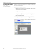
Chapter 8 Wiring Diagrams
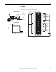
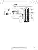
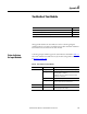
1756-OW16I
ControlLogix AC (10...240V) DC (5...125V) isolated contact module
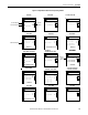
12
34
56
78
910
1112
1314
1516
1718
1920
2122
2324
2526
2728
2930
3132
3334
3536
Nonisolated
Wiring
Isolated Wiring
Daisy Chain
to Other RTBs
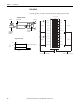
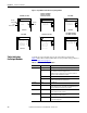
1756-OW16I
L1-0
L1-1
L1-2
L1-3
L1-8
L1-4
L1-5
L1-6
L1-7
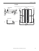
L1-9
L1-10
L1-11
L1-12
L1-13
L1-14
L1-15
Not Used
OUT-0
OUT-1 N.O.
OUT-2 N.O.
OUT-3 N.O.
OUT-8 N.O.
OUT-4 N.O.
OUT-5 N.O.
OUT-6 N.O.
OUT-7 N.O.
Not Used
OUT-9 N.O.
OUT-10 N.O.
OUT-11 N.O.
OUT-12 N.O.
OUT-13 N.O.
OUT-14 N.O.
OUT-15 N.O
Not Used
L1
Jumper Bar
(Cut to Length)
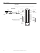
DC-4 (-)
L2
L1-15
L2-0
DC-4 (+)
L1-0
L1-2
L2-2
ControlLogix
Backplane
Interface
Display
OUT
L1
+24V
Simplified Schematic
Additional jumper bars may be purchased
by using catalog number 1756-JMPR.