
Owner's manual

144 Rockwell Automation Publication 1756-UM058G-EN-P - November 2012
Chapter 8 Wiring Diagrams
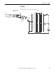
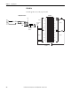
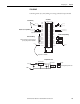
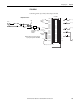
1756-IB16I
ControlLogix DC (10...30V) isolated input module
1
3
5
7
019
2111
4131
6151
8171
0291
2212
4232
6252
8272
0392
2313
4333
6353
(+)
(+)
+
–
+
–
Nonisolated
Wiring
Isolated
Wi ri n g
Daisy Chain to Other RTBs
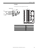
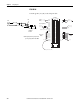
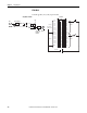
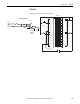
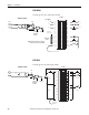
1756-IB16I
GND-0
GND-1
GND-2
GND-3
GND-8
GND-4
GND-5
GND-6
GND-7
Not Used
GND-9
GND-10
GND-11
GND-12
GND-13
GND-14
GND-15
GND-15
IN-0
IN-1
IN-2
IN-3
IN-8
IN-4
IN-5
IN-6
IN-7
Not Used
IN-9
IN-10
IN-11
IN-12
IN-13
IN-14
IN-15
Not Used
DC-5 (-)
DC (-)
Jumper Bar (Cut to Length)
DC-6 (-)
DC-5 (+)
DC-6 (+)
DC (+)
DC-0 (+)
DC-1 (+)
DC-0 (-)
DC-1 (-)
Source Input Wiring
Sink Input
Wiring
2
4
6
8
Additional jumper bars may be purchased
by using catalog number 1756-JMPR.
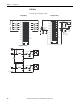
ControlLogix
Backplane
Interface
Display
GND-0
IN-0
+5V
GND