
Owner's manual

Rockwell Automation Publication 1756-UM058G-EN-P - November 2012 115
Install ControlLogix I/O Modules Chapter 6
To see a listing of the IFMs available for use with the ControlLogix analog I/O
modules, see Appendix
G.
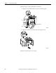
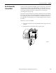
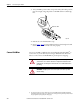
This chapter explains the general guidelines for wiring your digital I/O modules,
including grounding the cable and connecting the wires to each RTB type.
The following table shows each module catalog number and the corresponding
page with the wiring diagram.
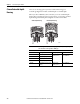
ATTENTION: When using the 1756-TBCH, do not wire more than two 0.33...1.3
mm
2
(22...16 AWG) conductors on any single terminal. Use only the same size
wires with no intermixing of solid and stranded wire types.
When using the 1756-TBS6H, do not wire more than 1 conductor on any single
terminal.
When using the 1756-TBNH, do not wire more than two 0.33...2.1 mm
2
(22...14 AWG) conductors on any single terminal. Use only the same size wires with
no intermixing of solid and stranded wire types.
When using the 1756-TBSH, do not wire more than 1 conductor on any single
terminal.
Cat. No. Page Cat. No. Page
1756-IA8D 139 1756-OA16I 157
1756-IA16 139 1756-OB8 158
1756-IA16I 140 1756-OB8EI 159
1756-IA32 141 1756-OB8I 160
1756-IB16 142 1756-OB16D 161
1756-IB16D 143 1756-OB16E 162
1756-IB16I 144 1756-OB16I 163
1756-IB16IF 145 1756-OB16IEF 164
1756-IB32 146 1756- 165
1756-IC16 147 1756-OB16IS 166
1756-IG16 148 1756-OB32 167
1756-IH16I 149 1756-OC8 168
1756-IM16I 150 1756-OG16 169
1756-IN16 150 1756-OH81 170
1756-IV16 151 1756-ON8 171
1756-IV32 152 1756-OV16E 172
1756-OA8 153 1756-OV32E 173
1756-OA8D 154 1756-OW16I 174
1756-OA8E 155 1756-OX8I 175
1756-OA16 156