
Installation Instructions User Manual

50 Rockwell Automation Publication 1756-IN005C-EN-P - March 2014
Chapter 2 Install Chassis and Redundant Power Supplies
Use 2.5 mm (14 AWG) solid or stranded-copper wire rated at 90 °C (194 °F), or
greater, 1.2 mm (3/64 in.) insulation maximum to connect power. Tighten the
terminals to a torque of 0.8 N•m (7 lb•in).
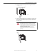
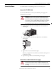
Connect the power as shown in Figure 35
.
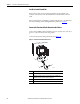
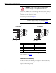
Figure 35 - Power Connection
For recommendations on how to route the wiring in your redundant power
supply application, see page 45
.
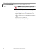
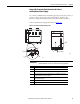
Connect the Solid-state Relay
A solid-state relay on your redundant power supplies can be connected to any
compatible monitoring or signaling device. This connection indicates if the
supplies are functioning properly.
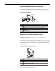
ATTENTION: Do not wire more than 1 conductor on any single terminal.
Use 15 A time-delay type fuse in all ungrounded power connections.
IMPORTANT
The power supplies’ voltage input connections are auto-sensing.
You do not use a jumper, for example, a 120/240V AC jumper, when
connecting external power to the power supply, as shown in Figure 35
.
1756-PA75R/A (AC) 1756-PB75R/A (DC)
1
3
2
5
45839
4
1
3
2
5
45840
4
Item Description, 1756-PA75R/A (AC) Description, 1756-PB75R/A (DC)
1 L1 (high side of line power) Not used
2 Not used DC+ (positive supply)
3 L2 (low side of line power) Not used
4 Not used DC- (negative supply return)
5 2.5 mm² (14 AWG) solid or stranded-copper wire rated at 90 °C (194 °F), or greater,
1.2 mm (3/64 in.) insulation max