
Installation Instructions User Manual

Rockwell Automation Publication 1756-IN005C-EN-P - March 2014 45
Install Chassis and Redundant Power Supplies Chapter 2
Ground the Chassis
Complete these steps to properly ground your system.
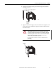
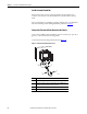
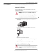
Figure 30
shows an example grounding configuration. After you complete the
grounding steps, your system looks similar to this figure.
Figure 30 - Grounding Configuration Example
Use these guidelines when connecting the grounding:
• Use a steel enclosure to guard against electromagnetic interference (EMI).
• Install a bonding wire for electrical contact between the enclosure door
and the enclosure; do not rely on the hinge.
• Make sure the enclosure-door viewing window is a laminated screen or a
conductive optical substrate (to block EMI).
Grounding Step Page
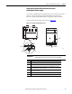
Install a Central Ground Bus 46
Connect the Functional Earth Ground on the Chassis 46
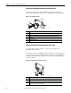
Connect the Protective Earth Ground on the Chassis and
Redundant Power Supply
47
Connect the Grounding Conductors to the Ground Bus 48
Connect Ground Bus to Grounding-electrode System 48
TIP
To minimize the resistance between the chassis and ground connection, keep
wire lengths as short as possible.
Functional Earth Ground, page 46
Protective Earth
Ground, page 47
Cabinet
To Grounding-electrode System
45836
Ground Bus
8.3 mm² (8 AWG) solid
or stranded-copper
wire rated at 90 °C
(194 °F) or greater
2.1 mm² (14 AWG) solid
or stranded-copper
wire rated at 90 °C
(194 °F) or greater