
Installation Instructions User Manual

36 Rockwell Automation Publication 1756-IN005C-EN-P - March 2014
Chapter 2 Install Chassis and Redundant Power Supplies
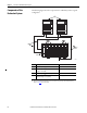
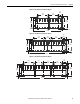
Dimensions are in cm (in.).
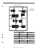
Figure 18 - Minimum Spacing Requirements
45828 (2)
15.3 (6.0)
10.2
(4.0)
12.7
(5.0)
5.1 (2.0)
5.1 (2.0)
15.3 (6.0)
10.2
(4.0)
10.2
(4.0)
15.3
(6.0)
2.55
(1.0)
12.7
(5.0)
12.7
(5.0)
5.1 (2.0)
12.7 (5.0)
The 10.2 (4.0) measurement
to the side of the enclosure
can include the wireway on
the right side of the chassis.
15.3 (6.0)
15.3 (6.0)
15.3 (6.0)
12.7
(5.0)
12.7
(5.0)
12.7
(5.0)
WIREWAY
WIREWAY
W
I
R
E
W
A
Y
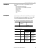
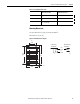
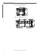
Table 8 - Spacing Requirements, Top and Bottom
From a To a chassis
requires this space, min
To a redundant power supply
requires this space, min
Cabinet 15.3 cm (6.0 in.) 10.2 cm (4.0 in.), 12.7 cm (5.0 in.) (only
bottom)
Chassis or other heat source 15.3 cm (6.0 in.) 15.3 cm (6.0 in.)
Wireway 5.1 cm (2.0 in.) 5.1 cm (2.0 in.), 2.7 cm (5.0 in.) (only
bottom)
Table 9 - Spacing Requirements, Sides
From a To a chassis
requires this space, min
To a redundant power supply
requires this space, min
Cabinet 10.2 cm (4.0 in.), 12.7 cm (5.0 in.) (only left
side)
10.2 cm (4.0 in.)