
Installation Instructions User Manual

Rockwell Automation Publication 1756-IN005C-EN-P - March 2014 35
Install Chassis and Redundant Power Supplies Chapter 2
Plan the System
Use the following information to assist you in planning your system.
Redundant Power Supply and Chassis Compatibility
The redundant power supplies and chassis adapter are compatible with only
standard, Series B, ControlLogix chassis.
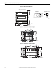
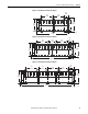
Spacing Requirements
Use the following information to plan your installation.
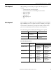
Table 7 - Chassis Compatibility
Power Supply Cat. No. Chassis Cat. No.
1756-PA75R 1756-A4/B, 1756-A7/B, 1756-A10/B, 1756-A13/B, 1756-A17/B,
1756-A4LXT, 1756-A5XT, 1756-A7LXT, 1756-A7XT
1756-PB75R
1756-PAXTR 1756-A4/B, 1756-A7/B, 1756-A10/B, 1756-A13/B, 1756-A17/B,
1756-A4LXT, 1756-A5XT, 1756-A7LXT, 1756-A7XT
1756-PBXTR
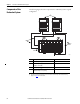
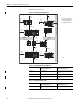
IMPORTANT
Make sure you meet the minimum spacing requirements specified:
• 10.2 cm (4.0 in.) between redundant power supplies and cabinet housing
the control system
• 12.7 cm (5.0 in.) below redundant power supply for 1756-CPR2 cable
routing and connection
• 2.55 cm (1.0 in.) between redundant power supplies
• 15.3 cm (6.0 in.) between chassis and heat source
• 5.1 cm (2.0 in.) between wireway and top or bottom of chassis or
redundant power supply
• 12.7 cm (5.0 in.) of clearance next to the chassis adapter for 1756-CPR2
cable routing to conform to cable bend radius
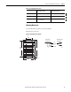
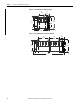
Chassis and redundant power supplies are intended to be mounted only
horizontally. Do not mount vertically.
The 1756-CPR2 cable has a bend radius of 12.7 cm (5.0 in.). The chassis must
have a minimum clearance of 12.7 cm (5.0 in.) on the left side in order to
properly route and connect the 1756-CPR2 cable. The redundant power
supplies must have a minimum clearance of 12.7 cm (5.0 in.) below the supply
to properly route and connect the 1756-CPR2 cable.