
Installation Instructions User Manual

Rockwell Automation Publication 1756-IN005C-EN-P - March 2014 29
Install Chassis and Power Supplies Chapter 1
Input Power Requirements
and Transformer Sizing
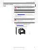
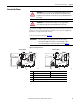
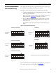
These graphs show the input power requirements for the power supplies, given
the power they are providing to the modules in the chassis.
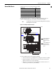
Follow these steps to determine the power requirements for your chassis.
1. Calculate the Backplane Power Load by adding the power draw (in Watts)
for all of the planned modules.
Refer to the module specification tables in the ControlLogix Selection
Guide, publication 1756-SG001
, for module power draws.
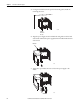
2. Locate the Backplane Power Load on the graph’s vertical (y) axis and
determine the corresponding Real Power (input-power) rating on the
horizontal (x) axis.
The Real Power value is the amount of power consumed by the power
supply.
Figure 17 - Power Supply Power Requirements
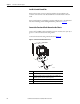
For more information about calculating the required power for your system, see
the ControlLogix Selection Guide, publication 1756-SG001
.
75
60
45
30
15
0
0 20 40 60 80 100 120
6
100
75
60
45
30
15
0
0 20 40 60 80 100 120
4
95
75
60
45
30
15
0
0 20 40 60 80 100 120
4
95
42
35
28
21
14
7
0
0 10 20 30 40 50 60 70
64
6
42
35
28
21
14
7
0
0 10 20 30 40 50 60
54
4
43895
1756-PA72/C, 1756-PA75/B (AC)
1756-PB72/C, 1756-PB75/B (DC)
43896
Real Power (Watts)
Backplane Power
Load (Watts)
Apparent Power (Watts) = Transformer Load (VA) = Real Power (Watts)
Backplane Power
Load (Watts)
Real Power (Watts)
1756-PH75/B, 1756-PC75/B (DC)
43618
Backplane Power
Load (Watts)
Real Power (Watts)
Backplane Power
Load (Watts)
Real Power (Watts)
1756-PBXT (DC)
1756-PAXT (AC)
Backplane Power
Load (Watts)
45808
45809
Real Power (Watts)