Installation Instructions ControlLogix Chassis and Power Supply Standard Chassis Catalog Numbers 1756-A4, 1756-A10, 1756-A13, 1756-A17 ControlLogix-XT Chassis Catalog Numbers 1756-A4LXT, 1756-A5XT, 1756-A7XLT, 1756-A7XT Standard Power Supplies Catalog Numbers 1756-PA72, 1756-PA75, 1756-PB72, 1756-PB75, 1756-PC75, 1756-PH75 ControlLogix-XT Power Supplies Catalog Numbers 1756-PAXT, 1756-PBXT Redundant Power Supplies Catalog Numbers 1756-PA75R, 1756-PB75R Redundant Power Supplies Chassis Adapter Catalog Numbe
Important User Information Read this document and the documents listed in the additional resources section about installation, configuration, and operation of this equipment before you install, configure, operate, or maintain this product. Users are required to familiarize themselves with installation and wiring instructions in addition to requirements of all applicable codes, laws, and standards.
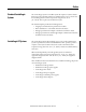
Summary of Changes This manual contains new and updated information. Changes throughout this revision are marked by change bars, as shown to the right of this paragraph. New and Updated Information The following components were added to these installation instructions.
Summary of Changes Notes: 4 Rockwell Automation Publication 1756-IN005C-EN-P - March 2014
Table of Contents Preface Standard ControlLogix Systems . . . . . . . . . . . . . . . . . . . . . . . . . . . . . . . . . . . . . 7 ControlLogix-XT Systems . . . . . . . . . . . . . . . . . . . . . . . . . . . . . . . . . . . . . . . . . . 7 Where to Start . . . . . . . . . . . . . . . . . . . . . . . . . . . . . . . . . . . . . . . . . . . . . . . . . . . . . 8 Installation Advisories . . . . . . . . . . . . . . . . . . . . . . . . . . . . . . . . . . . . . . . . . . . . . . 9 Additional Resources . . . .
Table of Contents Connect the Protective Earth Ground on the Chassis and Redundant Power Supply . . . . . . . . . . . . . . . . . . . . . . . . . . . . . . . . . Connect the Grounding Conductors to the Ground Bus . . . . . . . . . Connect Ground Bus to Grounding-electrode System . . . . . . . . . . . Connect the Power . . . . . . . . . . . . . . . . . . . . . . . . . . . . . . . . . . . . . . . . . . . . . . . Connect the 1756-CPR2 Cable. . . . . . . . . . . . . . . . . . . . . . . . . . . . . . . .
Preface Standard ControlLogix Systems The ControlLogix system is a modular system that requires a 1756 I/O chassis that houses various modules. Chassis are available with 4, 7, 10, 13, and 17 slots for standard applications where temperatures range from 0…60 °C (32…140 °F). You can place any module into any slot.
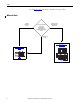
Preface Use the Where to Start chart below to determine the steps to follow.
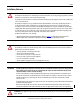
Preface Installation Advisories ATTENTION: Environment and Enclosure This equipment is intended for use in a Pollution Degree 2 industrial environment, in overvoltage Category II applications (as defined in IEC 60664-1), at altitudes up to 2000 m (6562 ft) without derating. This equipment is not intended for use in residential environments and may not provide adequate protection to radio communication services in such environments. This equipment is supplied as open-type equipment.
Preface European Hazardous Location Approval The following applies when the product bears the Ex Marking. This equipment is intended for use in potentially explosive atmospheres as defined by European Union Directive 94/9/EC and has been found to comply with the Essential Health and Safety Requirements relating to the design and construction of Category 3 equipment intended for use in Zone 2 potentially explosive atmospheres, given in Annex II to this Directive.
Preface Additional Resources These documents contain additional information concerning related products from Rockwell Automation. Resource Description ControlLogix Selection Guide, publication 1756-SG001 Provides overview of the ControlLogix system and its products. ControlLogix Chassis Specifications Technical Data, publication 1756-TD006 Provides technical specifications for ControlLogix chassis.
Preface 12 Rockwell Automation Publication 1756-IN005C-EN-P - March 2014
Chapter 1 Install Chassis and Power Supplies This chapter describes how to install standard and ControlLogix-XT versions of the 1756 chassis with nonredundant power supplies. Tools Required When installing either the standard or ControlLogix-XT versions of your 1756 chassis and power supplies, the following items are required: • 3.18 mm (0.125 in.) slotted screwdriver • 6.35 mm (0.25 in.
Chapter 1 Install Chassis and Power Supplies Table 2 - Total Parts Required Per Chassis Chassis Number of Mounting Tabs Total Parts Required Per Chassis With SEM Screws Without SEM Screws 1756-A13 4 top 4 bottom • • • • 4 Phillips screws 4 flat washers 4 split-lock washers 4 SEM screws • • • • 8 Phillips screws 4 flat washers 4 split-lock washers 4 star washers 1756-A17 5 top 5 bottom • • • • 5 Phillips screws 5 flat washers 5 split-lock washers 5 SEM screws • • • • 10 Phillips screws 5 fla
Install Chassis and Power Supplies Plan the System Chapter 1 Use the following information to assist you in planning your system. Power Supply and Chassis Compatibility The chassis series you have determines the power supply you can use. The following table lists the chassis that can be installed with each power supply. Table 3 - Chassis Compatibility Power Supply Cat. No. Chassis Cat. No.
Chapter 1 Install Chassis and Power Supplies Spacing Requirements Use the following information to plan your installation. IMPORTANT Make sure you meet the minimum spacing requirements specified. Allow 15.3 cm (6.0 in.) between chassis and a heat source, and allow 5.1 cm (2.0 in.) between a wireway and the top or bottom of a chassis. Chassis are intended to be mounted only horizontally. Do not mount vertically. Dimensions are in cm (in.). 15.3 (6.0) 15.3 (6.0) The 10.2 (4.
Install Chassis and Power Supplies Chapter 1 Mounting Dimensions Use these dimensions to plan your chassis installation. Dimensions are in cm (in.). Figure 1 - Chassis Common Dimensions Top Mounting Hole Diameter Bottom Mounting Hole Diameter 0.55 (0.217) 1.1 (0.433) 45797 0.78 (0.31) Right-side View of All ControlLogix-XT Chassis Right-side View of All Standard Chassis 16.9 (6.65) 16.9 (6.65) 14.5 (5.71) 14.9 (5.87) 43591 45865 Figure 2 - 1756-A4 Chassis and Power Supply 7.0 (2.76) 4.71 (1.
Chapter 1 Install Chassis and Power Supplies Figure 3 - 1756-A7 Chassis and Power Supply 4.71 (1.85) 17.5 (6.89) 15.8 (6.22) 14.5 (5.70) 16.9 (6.65) 36.7 (14.47) 43593 Figure 4 - 1756-A10 Chassis and Power Supply 14.0 (5.51) 14.0 (5.51) 15.8 (6.22) 5.7 (2.25) 14.5 (5.70) 16.9 (6.65) 48.3 (19.02) 43594 Figure 5 - 1756-A13 Chassis and Power Supply 10.5 (4.13) 14.0 (5.51) 15.8 (6.22) 5.7 (2.25) 14.5 (5.70) 58.8 (23.13) 18 14.0 (5.
Install Chassis and Power Supplies Chapter 1 Figure 6 - 1756-A17 Chassis and Power Supply 13.3 (5.22) 14.0 (5.51) 4.7 (1.85) 13.3 (5.22) 14.0 (5.51) 16.9 14.5 (6.65) (5.70) 15.8 (6.22) 73.8 (29.04) 43596 Figure 7 - 1756-A4LXT Chassis and Power Supply 7.0 (2.76) 6.3 (2.48) 15.8 (6.22) 14.5 (5.72) 27.8 (10.96) 16.9 (6.65) 45798 Figure 8 - 1756-A5XT Chassis and Power Supply 14.0 (5.51) 15.8 (6.22) 14.0 (5.51) 7.3 (2.87) 14.5 (5.72) 49.8 (19.
Chapter 1 Install Chassis and Power Supplies Figure 9 - 1756-A7LXT Chassis and Power Supply 6.3 (2.48) 17.5 (6.89) 15.8 (6.22) 14.5 (5.72) 16.9 (6.65) 38.3 (15.10) 45800 Figure 10 - 1756-A7XT Chassis and Power Supply 14.0 (5.51) 15.8 (6.22) 14.5 (5.70) 49.8 (19.62) 20 14.0 (5.51) 7.3 (2.87) Rockwell Automation Publication 1756-IN005C-EN-P - March 2014 16.9 (6.
Install Chassis and Power Supplies Install the Chassis and Power Supply Chapter 1 After planning your system, use these instructions to properly install the standard or ControlLogix-XT versions of your 1756 chassis and power supplies. ATTENTION: Do not drill holes above an installed chassis. Metal chips from drilling can damage the backplane and cause intermittent operation. IMPORTANT Chassis are intended to be mounted only horizontally. Do not mount vertically. 1.
Chapter 1 Install Chassis and Power Supplies 5. Leaving the far-left bottom tab open for functional ground, install the remaining tab screws. 20290-M Leave farleft bottom tab open. 6. Align the power-supply circuit board with the card guides on the left side of the chassis and slide the power supply back until it is flush with the front of the chassis. Card Guide 43614 7. Tighten the top and bottom screws to fasten the power supply to the chassis.
Install Chassis and Power Supplies Ground the Chassis Chapter 1 Complete these steps to properly ground your chassis. Grounding Step Page Install a Central Ground Bus 24 Connect the Functional Earth Ground on the Chassis 24 Connect the Protective Earth Ground 25 Connect the Grounding Conductors to the Ground Bus 26 Connect Ground Bus to Grounding-electrode System 26 The following figure shows an example grounding configuration.
Chapter 1 Install Chassis and Power Supplies Install a Central Ground Bus Each enclosure must contain a central ground bus. The ground bus is the common connection for each chassis within the enclosure and the enclosure itself. For more information on installing a central ground bus, refer to the Industrial Automation Wiring and Grounding Guidelines, publication 1770-4.1. Connect the Functional Earth Ground on the Chassis Use 8.
Install Chassis and Power Supplies Chapter 1 Connect the Protective Earth Ground Use 2.1 mm2 (14 AWG) solid or stranded-copper wire rated at 90 °C (194 °F) or greater to connect the protective earth ground. Tighten the nuts on the protective earth ground terminal stud to a torque of 16.27 N•m (12 lb•in). Connect the functional earth ground as shown in Figure 13.
Chapter 1 Install Chassis and Power Supplies Connect the Grounding Conductors to the Ground Bus Connect the equipment grounding conductors (functional and protective earth ground) directly from each chassis to an individual bolt on the ground bus.
Install Chassis and Power Supplies Chapter 1 Connect the Power WARNING: If you connect or disconnect wiring while the field-side power is on, an electrical arc can occur. This can cause an explosion in hazardous location installations. Be sure that power is removed or the area is nonhazardous before proceeding. ATTENTION: Do not wire more than 1 conductor on any single terminal. Use 15 A time-delay type fuse in all ungrounded power connections. Use 2.
Chapter 1 Install Chassis and Power Supplies Remove the Protective Label ATTENTION: Make sure the chassis is mounted and all panel fabrication is complete before you remove the protective label. This label protects the power supply from metal shavings falling inside the power supply and damaging it during operation. Remove the plastic label from the top of the power supply. 20264b-M Apply Power to the Chassis Turn on the power.
Install Chassis and Power Supplies Chapter 1 These graphs show the input power requirements for the power supplies, given the power they are providing to the modules in the chassis. Input Power Requirements and Transformer Sizing Follow these steps to determine the power requirements for your chassis. 1. Calculate the Backplane Power Load by adding the power draw (in Watts) for all of the planned modules.
Chapter 1 Install Chassis and Power Supplies Troubleshoot the Power Supply All ControlLogix power supplies have a green status indicator that remains ON during normal operation. Status Indicator 45810 If the indicator turns OFF during operation, take these steps to troubleshoot the power supply. 1. Verify that the line voltage is within the specified range. 2. If the indicator remains OFF, turn off the power. 3. Loosen the screws holding the power supply to the chassis.
Chapter 2 Install Chassis and Redundant Power Supplies This chapter describes how to install standard and ControlLogix-XT versions of the 1756 chassis with redundant power supplies. Redundant Power Supplies The redundant power supply system provides additional uptime protection for chassis used in critical applications.
Chapter 2 Install Chassis and Redundant Power Supplies The following figure shows the components of a redundant system in a typical configuration. Components of the Redundant System 1 2 4 3 42655 Item Description Cat. No. 1 Redundant power supply 1756-PA75R/A and/or 1756-PB75R/A 2 Redundant power supply cable(1) 1756-CPR2 (Length = 0.91 m [3 ft]) 3 Redundant power supply chassis adapter 4 (2) Annunciator wiring (Maximum length = 10 m [32.
Install Chassis and Redundant Power Supplies Chapter 2 Tools Required When installing your chassis and power supplies, the following items are required: • 3.18 mm (0.125 in.) slotted screwdriver • 6.35 mm (0.25 in.) slotted or #2 Phillips-head screwdriver • Torque screwdriver • Needle-nose pliers • Crimping tool • Wire-stripping tool • Drill Parts Required Each redundant power supply requires four, #10 Phillips screws for installation.
Chapter 2 Install Chassis and Redundant Power Supplies Follow These Steps Plan the System page 35 Install the Chassis and Chassis Adapter page 42 Install the Redundant Power Supplies page 44 Ground the Chassis page 45 Connect the Power page 49 Remove the Protective Label page 52 Apply Power to the Chassis page 52 34 Rockwell Automation Publication 1756-IN005C-EN-P - March 2014
Install Chassis and Redundant Power Supplies Plan the System Chapter 2 Use the following information to assist you in planning your system. Redundant Power Supply and Chassis Compatibility The redundant power supplies and chassis adapter are compatible with only standard, Series B, ControlLogix chassis. Table 7 - Chassis Compatibility Power Supply Cat. No. Chassis Cat. No.
Chapter 2 Install Chassis and Redundant Power Supplies Dimensions are in cm (in.). Figure 18 - Minimum Spacing Requirements 15.3 (6.0) 10.2 (4.0) 10.2 (4.0) 12.7 (5.0) 2.55 (1.0) The 10.2 (4.0) measurement to the side of the enclosure can include the wireway on the right side of the chassis. 10.2 (4.0) 15.3 (6.0) 12.7 (5.0) 12.7 (5.0) 5.1 (2.0) 15.3 (6.0) WIREWAY 5.1 (2.0) WIREWAY 5.1 (2.0) 12.7 (5.0) 12.7 (5.0) 15.3 (6.0) 12.7 (5.0) W I R E W A Y 15.3 (6.0) 12.7 (5.0) 45828 (2) 15.3 (6.
Install Chassis and Redundant Power Supplies Chapter 2 Table 9 - Spacing Requirements, Sides From a To a chassis requires this space, min To a redundant power supply requires this space, min Chassis or other heat source 7.7 cm (3.0 in.), 12.7 cm (5.0 in.) (only left side) 7.7 cm (3.0 in.) Redundant power supply 7.7 cm (3.0 in.), 12.7 cm (5.0 in.) (only left side) 2.55 cm (1.0 in.) Wireway No minimum spacing required, 12.7 cm (5.0 in.
Chapter 2 Install Chassis and Redundant Power Supplies Figure 20 - Chassis Common Dimensions Right-side View of All Chassis Top Mounting Tab Diameter Bottom Mounting Tab Diameter 0.55 (0.217) 1.1 (0.433) 16.9 (6.65) 0.78 (0.31) 45797 43591 14.5 (5.71) Figure 21 - 1756-A4 Chassis and Chassis Adapter 7.0 (2.76) 4.7 (1.85) 15.8 (6.22) 14.5 (5.70) 16.9 (6.65) 18.6 (7.32) 45830 Figure 22 - 1756-A7 Chassis and Chassis Adapter 17.5 (6.89) 16.9 14.5 (6.65) (5.70) 15.8 (6.22) 29.1 (11.46) 38 4.
Install Chassis and Redundant Power Supplies Chapter 2 Figure 23 - 1756-A10 Chassis and Chassis Adapter 14.0 (5.51) 5.71 (2.25) 14.0 (5.51) 15.8 (6.22) 14.5 (5.70) 40.6 (15.98) 16.9 (6.65) 45832 Figure 24 - 1756-A13 Chassis and Chassis Adapter 10.5 (4.13) 14.0 (5.51) 14.0 (5.51) 5.71 (2.25) 15.8 (6.22) 14.5 (5.70) 51.1 (20.12) 16.9 (6.65) 45833 Figure 25 - 1756-A17 Chassis and Chassis Adapter 14.0 (5.51) 13.3 (5.22) 14.0 (5.51) 13.3 (5.22) 4.7 (1.85) 16.9 14.5 (6.65) (5.70) 15.8 (6.
Chapter 2 Install Chassis and Redundant Power Supplies Figure 26 - 1756-A4LXT Chassis and Chassis Adapter 7.0 (2.76) 6.29 (2.48) 16.9 (6.65) 14.5 (5.70) 15.8 (6.22) 20.1 (7.91) 45866 Figure 27 - 1756-A5XT/A7XT Chassis and Chassis Adapter 14.0 (5.51) 14.0 (5.51) 16.9 14.5 (6.65) (5.70) 15.8 (6.22) 42.1 (16.57) 40 7.3 (2.
Install Chassis and Redundant Power Supplies Chapter 2 System Configuration Recommendations We recommend you use one of these methods to configure your redundant power supply system.
Chapter 2 Install Chassis and Redundant Power Supplies Install the Chassis and Chassis Adapter After planning your system, use the instructions below to properly install your chassis and 1756-PSCA2 chassis adapter. ATTENTION: Do not drill holes above an installed chassis. Metal chips from drilling can damage the backplane and cause intermittent operation. IMPORTANT Chassis are intended to be mounted only horizontally. Do not mount vertically. 1.
Install Chassis and Redundant Power Supplies Chapter 2 5. Leaving the far-left bottom tab open for functional ground, install the remaining tab screws. 20290-M Leave the farleft bottom tab open. 6. Align the 1756-PSCA2 adapter’s circuit board with the card guides on the left side of the chassis and slide the adapter back until it is flush with the front of the chassis. WARNING: If you connect or disconnect the 1756-CPR2 cables while either backplane power source is on, an electrical arc can occur.
Chapter 2 Install Chassis and Redundant Power Supplies Install the Redundant Power Supplies Follow these steps to install your redundant power supplies. ATTENTION: Do not drill holes for a redundant power supply above installed equipment. Metal chips from drilling can damage the backplane and cause intermittent operation. 1. Drill holes in the back panel of the enclosure for the redundant power supply. See the Spacing Requirements on page 35 for assistance in hole placement. 2.
Install Chassis and Redundant Power Supplies Ground the Chassis Chapter 2 Complete these steps to properly ground your system. Grounding Step Page Install a Central Ground Bus 46 Connect the Functional Earth Ground on the Chassis 46 Connect the Protective Earth Ground on the Chassis and Redundant Power Supply 47 Connect the Grounding Conductors to the Ground Bus 48 Connect Ground Bus to Grounding-electrode System 48 Figure 30 shows an example grounding configuration.
Chapter 2 Install Chassis and Redundant Power Supplies Install a Central Ground Bus Each enclosure must contain a central ground bus. The ground bus is the common connection for each chassis within the enclosure and the enclosure itself. For more information on installing a central ground bus, refer to the Industrial Automation Wiring and Grounding Guidelines, publication 1770-4.1. Connect the Functional Earth Ground on the Chassis Use 8.
Install Chassis and Redundant Power Supplies Chapter 2 Connect the Protective Earth Ground on the Chassis and Redundant Power Supply Use 2.1 mm2 (14 AWG) solid or stranded-copper wire rated at 90 °C (194 °F) or greater to connect the protective earth ground. Tighten the nuts on the protective earth ground terminal stud to a torque of 16.27 N•m (12 lb•in). Connect the functional earth ground as shown in Figure 32.
Chapter 2 Install Chassis and Redundant Power Supplies Connect the Grounding Conductors to the Ground Bus Connect the equipment grounding conductors (functional and protective earth ground) directly from each chassis to an individual bolt on the ground bus.
Install Chassis and Redundant Power Supplies Connect the Power Chapter 2 Use the information in the following sections to connect the power. Connect the 1756-CPR2 Cable Use the 1756-CPR2 cable to connect your redundant power supply to the 1756-PSCA2 chassis adapter. WARNING: If you connect or disconnect the 1756-CPR2 cables while either backplane power source is on, an electrical arc can occur. This could cause an explosion in hazardous location installations.
Chapter 2 Install Chassis and Redundant Power Supplies ATTENTION: Do not wire more than 1 conductor on any single terminal. Use 15 A time-delay type fuse in all ungrounded power connections. Use 2.5 mm2 (14 AWG) solid or stranded-copper wire rated at 90 °C (194 °F), or greater, 1.2 mm (3/64 in.) insulation maximum to connect power. Tighten the terminals to a torque of 0.8 N•m (7 lb•in). Connect the power as shown in Figure 35. IMPORTANT The power supplies’ voltage input connections are auto-sensing.
Install Chassis and Redundant Power Supplies Chapter 2 The relays are closed during standard operation. The solid-state relay contacts open if either of these events occur: • One or both of the supplies fail. In this case, the contact opens on the failed supply (or supplies), and the input module alerts you to the failure through the controller program. • The connected redundant power supplies are turned OFF.
Chapter 2 Install Chassis and Redundant Power Supplies Remove the Protective Label ATTENTION: Make sure the power supply is mounted and all panel fabrication is complete before you remove the protective label. This label protects the power supply from metal shavings falling inside the power supply and damaging it during operation. Remove the plastic label from the top of the power supply. 42841 Apply Power to the Chassis Turn on the power.
Install Chassis and Redundant Power Supplies Chapter 2 These graphs show the input power requirements for the power supplies, given the power they are providing to the modules in the chassis. Input Power Requirements and Transformer Sizing Follow these steps to determine the power requirements for your chassis. 1. Calculate the Backplane Power Load by adding the power draw (in Watts) for all of the planned modules.
Chapter 2 Install Chassis and Redundant Power Supplies The redundant power supplies have a green status indicator for power and an amber status indicator for non-redundancy. Troubleshoot the Redundant Power Supplies Power Non-red 45843 The following table describes how to use the status indicators to troubleshoot your redundant power supplies. Power Indicator Non-red Indicator Description Take This Action Solid green Off Both power supplies are operating properly.
Install Chassis and Redundant Power Supplies Remove or Replace a Redundant Power Supply Chapter 2 Use this information to remove or replace a redundant power supply. WARNING: Remove or replace power supplies only when backplane and power supply power are removed or the area is known to be nonhazardous. Removal or replacement of a power supply in a hazardous area can cause an electrical arc across the contacts if backplane power is still applied.
Chapter 2 Install Chassis and Redundant Power Supplies Remove or Replace a Chassis Adapter Use this information to remove or replace a redundant power supply. Remove a Chassis Adapter Follow these steps to remove a chassis adapter. 1. Turn the redundant power supplies OFF. 2. Disconnect the 1756-CPR2 cable. 3. Push the top and bottom locking tabs on the chassis adapter to the side and pull the module off the chassis.
Install Chassis and Redundant Power Supplies Chapter 2 Notes: Rockwell Automation Publication 1756-IN005C-EN-P - March 2014 57
Chapter 2 58 Install Chassis and Redundant Power Supplies Rockwell Automation Publication 1756-IN005C-EN-P - March 2014
Rockwell Automation Support Rockwell Automation provides technical information on the Web to assist you in using its products. At http://www.rockwellautomation.com/support you can find technical and application notes, sample code, and links to software service packs. You can also visit our Support Center at https://rockwellautomation.custhelp.com/ for software updates, support chats and forums, technical information, FAQs, and to sign up for product notification updates.