
Manual

Publication 1756-UM009C-EN-P - December 2010 97
Sourcing Current Loop Input Module (1756-IF6CIS) and Isolated Analog Voltage/Current Input Module (1756-IF6I) Chapter 5
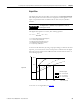
Notch Filter
An analog-to-digital convertor (ADC) filter removes line noise in your
application for each channel.
Choose a notch filter that most closely matches the anticipated noise
frequency in your application. Remember that each filter time affects the
response time of your module. Also, the highest frequency notch filter settings
also limit the effective resolution of the channel.
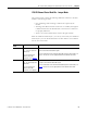
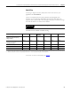
The table lists the available notch filter setting.
To see how to choose a notch filter, see
page 210
.
IMPORTANT
60 Hz is the default setting for the notch filter.
Notch Setting 10 Hz 50 Hz 60 Hz
(Default)
100 Hz 250 Hz 1000 Hz
Minimum Sample Time (RTS)
–
Integer mode
(1)
102 ms 22 ms 19 ms 12 ms 10 ms 10 ms
Minimum Sample Time (RTS)
–
Floating point mode
(2)
102 ms 25 ms 25 ms 25 ms 25 ms 25 ms
0…100% Step Response Time
(2)
400 ms + RTS 80 ms + RTS 68 ms + RTS 40 ms + RTS 16 ms + RTS 4 ms + RTS
-3dB Frequency 3 Hz 13 Hz 15 Hz 26 Hz 66 Hz 262 Hz
Effective Resolution 16 bits 16 bits 16 bits 16 bits 15 bits 10 bits
(1)
Integer mode must be used for RTS values lower than 25 ms. The minimum RTS value for the module will be dependent on the channel with the lowest notch filter setting.
(2)
Worst case setting time to 100% of a step change would include 0…100% step response time plus one RTS sample time.