
Manual

Publication 1756-UM009C-EN-P - December 2010 79
Non-isolated Analog Voltage/Current Input Modules (1756-IF16, 1756-IF8) Chapter 4
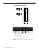
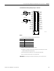
1756-IF16 Fault Reporting in
Floating Point Mode
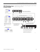
The illustration is an example of the fault reporting process for the 1756-IF16
module in floating point mode.
Module Fault Word
(described on
page 80
)
Channel Fault Word
(described on
page 80
)
Channel Status Words
(one for each channel–described
on
page 81
)
15 14 13 12 11
543210
54321076
15 = AnalogGroupFault
10 = Calibrating
9 = Cal Fault
14, 13, 12, & 11 are not used
7 = Ch7Fault
6 = Ch6Fault
5 = Ch5Fault
4 = Ch4Fault
3 = Ch3Fault
2 = Ch2Fault
1 = Ch1Fault
0 = Ch0Fault
7 = ChxCalFault
6 = ChxUnderrange
5 = ChxOverrange
4 = ChxRateAlarm
If set, any bit in the Channel Fault word, also sets the Analog
Group Fault in the Module Fault word
A channel calibration fault
sets the calibration fault in
the Module Fault word
Alarm bits 0…4 in the Channel Status word
do not set additional bits at any higher level.
You must monitor these conditions here.
The number of channel status words is
dependent on the wiring format used.
3 = ChxLAlarm
2 = ChxHAlarm
1 = ChxLLAlarm
0 = ChxHHAlarm
An underrange, overrange condition
sets appropriate Channel Fault bits
When the module is calibrating, all
bits in the Channel Fault word are set
10 9
987615 14 13 12 11 10
15 = Ch15Fault
14 = Ch14Fault
13 = Ch13Fault
12 = Ch12Fault
11 = Ch11Fault
10 = Ch10Fault
9 = Ch9Fault
8 = Ch8Fault
16 channels used in S.E. wiring
Eight channels used in Diff. wiring
Four channels used in H.S. Diff.
wiring
41512