
Manual

76 Publication 1756-UM0009C-EN-P - December 2010
Chapter 4 Non-isolated Analog Voltage/Current Input Modules (1756-IF16, 1756-IF8)
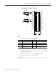
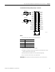
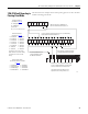
1756-IF8 Single-ended Current Wiring Example
12
34
56
78
910
1112
1314
1516
1718
1920
2122
2324
2526
2728
2930
3132
3334
3536
IN-0
IN-1
IN-2
IN-5
IN-3
IN-6
RTN
IN-7
IN-4
i RTN-0
i RTN-7
i RTN-4
i RTN-6
RTN
i RTN-5
i RTN-1
i RTN-2
i RTN-3
i
i
Not used
Not used
Not used
Not used
Not used
Not used
Not used
RTN
Not used
Not used
Not used
Not used
RTN
Not used
Not used
Not used
Not used
Not used
A
+
-
2-Wire
Transmitter
Shield Ground
Jumper Wires
NOTES:
1. All terminals marked RTN are connected internally.
2. For current applications, all terminals marked iRTN must be wired to terminals marked RTN.
3. A 249 Ω current loop resistor is located between IN-x and i RTN-x terminals.
4. Place additional loop devices (strip chart recorders, so forth) at the A location in the current loop.
5. Do not connect more than two wires to any single terminal.
User-provided
Loop Power