
Manual

68 Publication 1756-UM0009C-EN-P - December 2010
Chapter 4 Non-isolated Analog Voltage/Current Input Modules (1756-IF16, 1756-IF8)
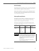
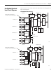
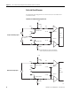
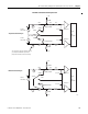
Field-side Circuit Diagrams
The field-side circuit diagrams are the same for both the 1756-IF16 and
1756-IF8 modules.
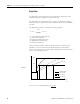
1756-IF16 and 1756-IF8 Voltage Input Circuit
43495
Single-ended Voltage Inputs
Differential Voltage Inputs
– 15V Note: Odd-numbered, single-ended channels
float to negative full scale when unconnected.
IN-0
i RTN-0
IN-1
i RTN-1
RTN
+
–
+ 15V
249 Ω 1/4 Watt
0.01 μF
Channel 0
16-bit
A/D
Converter
– 15V
20 MΩ
249 Ω 1/4 Watt
10 K 10 K
0.01 μF
Channel 1
V
20 MΩ
10 K 10 K
+
–
V
+
–
V
IN-0
i RTN-0
IN-1
i RTN-1
RTN
+ 15V
249 Ω 1/4 Watt
0.01 μF
Channel 0
16-bit
A/D
Converter
20 MΩ
249 Ω 1/4 Watt
10 K 10 K
0.01 μF
Channel 1
20 MΩ
10 K 10 K