
Manual

Publication 1756-UM009C-EN-P - December 2010 53
ControlLogix Analog I/O Module Features Chapter 3
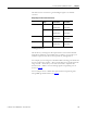
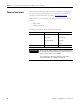
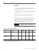
The table lists the conversions a generated digital signal to the number
of counts.
Floating point mode
This mode lets you change the data representation of the selected module.
Although the full range of the module does not change, you can scale your
module to represent I/O data in terms specific for your application.
For example, if you are using the 1756-IF6I module in floating point mode and
choose an input range of 0 mA…20 mA, the module can use signals within the
range of 0 mA…21 mA but you can scale the module to represent data
between 4 mA…20mA as the low and high signals in engineering units as
shown on
page 50
.
For an example of how to define data representation in engineering units
through RSLogix 5000 software, see
page 210
.
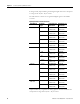
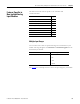
Output Signal to User Count Conversion
Output Module Available
Range
Low Signal and
User Counts
High Signal and
User Counts
1756-OF4/OF8 0…20 mA 0 mA
-32768 counts
21.2916 mA
32767 counts
+/- 10V -10.4336V
-32768 counts
10.4336V
32767 counts
1756-OF6CI 0…20 mA 0 mA
-32768 counts
21.074 mA
32767 counts
1756-OF6VI +/- 10V -10.517V
-32768 counts
10.517V
32767 counts