
Manual

Publication 1756-UM009C-EN-P - December 2010 335
Analog I/O Tag Definitions Appendix B
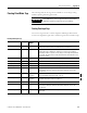
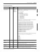
Ch0Config
RangeTypeNotch
INT 1756-IF6CIS,
1756-IF6I,
1756-IR6I,
1756-IT6I and
1756-IT6I2
Configures the channel’s input range, sensor type and notch filter settings. The
input range is bits 8…11 and determines the signal range the input channel
can detect. Input range values are as listed.
0 = -10…10V (1756-IF6I)
1 = 0…5V (1756-IF6I)
2 = 0…10V (1756-IF6I)
3 = 0…20 mA (1756-IF6CIS and 1756-IF6I)
4 = -12…78 mV (1756-IT6I and 1756-IT6I2)
5 = -12…30 mV (1756-IT6I and 1756-IT6I2)
6 = 1…487 Ω (1756-IR6I)
7 = 2…1,000 Ω (1756-IR6I)
8 = 4…2,000 Ω (1756-IR6I)
9 = 8…4,020 Ω (1756-IR6I)
Sensor type is bits 4…7 and selects the sensor type to use for linearization on
the 1756-IR6I, IT6I. Sensor types values are as listed.
0 =no linearization, Ω (1756-IR6I), mV (1756-IT6I and 1756-IT6I2)
1 = 100 Ω Platinum 385 (1756-IR6I) B (1756-IT6I and 1756-IT6I2)
2 = 200 Ω Platinum 385 (1756-IR6I), C (1756-IT6I and 1756-IT6I2)
3 = 500 Ω Platinum 385 (1756-IR6I), E (1756-IT6I and 1756-IT6I2)
4 = 1000 Ω Platinum 385 (1756-IR6I), J (1756-IT6I and 1756-IT6I2)
5 = 100 Ω Platinum 3916 (1756-IR6I), K (1756-IT6I and 1756-IT6I2)
6 = 200 Ω Platinum 3916 (1756-IR6I), N (1756-IT6I and 1756-IT6I2)
7 = 500 Ω Platinum 3916 (1756-IR6I), R (1756-IT6I and 1756-IT6I2)
8 = 1000 Ω Platinum 3916 (1756-IR6I), S (1756-IT6I and 1756-IT6I2)
9 = 10 Ω Copper 427 (1756-IR6I), T (1756-IT6I and 1756-IT6I2)
10 = 120 Ω Nickel 672 (1756-IR6I), TXK/XK (L) (1756-IT6I2)
11 = 100 Ω Nickel 618 (1756-IR6I), D (1756-IT6I2)
12 = 120 Ω Nickel 618 (1756-IR6I)
13 = 200 Ω Nickel 618 (1756-IR6I)
14 = 500 Ω Nickel 618 (1756-IR6I)
The notch filter provides superior frequency filtering at the selected value and
its harmonics. The notch filter is the lower nibble (bits 0…3).
0 = 10 Hz
1 = 50 Hz
2 = 60 Hz
3 = 100 Hz
4 = 250 Hz
5 = 1,000 Hz
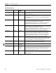
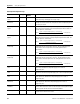
Ch0ConfigAlarm
Disable
BOOL All Disables all alarms for the channel.
Ch0ConfigProcess
AlarmLatch
BOOL All inputs Enables latching for all four process alarms: low, low low, high and high high.
Latching causes the process alarm to remain set until an unlatch service is
explicitly sent to the channel or alarm.
Ch0ConfigRate
AlarmLatch
BOOL All inputs Enables latching for the rate alarm. Latching causes the rate alarm to remain
set until an unlatch service is explicitly sent to the channel or alarm.
Ch0ConfigDigital
Filter
INT All inputs A non-zero value enables the filter, providing a time constant in milliseconds
used in a first order lag filter to smooth the input signal.
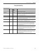
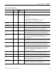
Floating Point Configuration Tags
Tag Name Data Type Applicable
Modu
les
Defi
nition