
Manual


Publication 1756-UM009C-EN-P - December 2010 329
Analog I/O Tag Definitions Appendix B
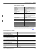
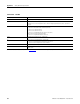
Integer Configuration Tags
Integer Configuration Tags
Tag Name Data Type Applicable
Modules
Definition
CJDisable BOOL All inputs (only
used for the
1756-IT6I and
1756-IT6I2)
Disables the cold junction sensor that turns off cold junction compensation
when linearizing thermocouple inputs.
RealTimeSample INT All input Determines how often the input signal is to be sampled in terms of
milliseconds.
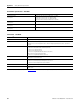
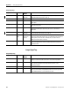
Ch0RangeNotch SINT 1756-IF6CIS,
1756-IF6I,
1756-IR6I,
1756-IT6I and
1756-IT6I2
Configures the channel’s input range and notch filter settings. The input range
is the upper nibble (bits 4…7) and determines the signal range the input
channel can detect. Input range values are as listed.
0 = -10…10V (1756-IF6I)
1 = 0…5V (1756-IF6I)
2 = 0…10V (1756-IF6I)
3 = 0…20 mA (1756-IF6CIS and 1756-IF6I)
4 = -12…78 mV (1756-IT6I and 1756-IT6I2)
5 = -12…30 mV (1756-IT6I and 1756-IT6I2)
6 = 1…487 Ω (1756-IR6I)
7 = 2…1,000 Ω (1756-IR6I)
8 = 4…2,000 Ω (1756-IR6I)
9 = 8…4,020 Ω (1756-IR6I)
The notch filter provides superior frequency filtering at the selected value and
its harmonics. The notch filter is the lowest nibble (bits 0…3).
0 = 10 Hz
1 = 50 Hz
2 = 60 Hz
3 = 100 Hz
4 = 250 Hz
5 = 1,000 Hz
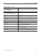
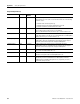
ProgToFaultEn BOOL All outputs The program to fault enable bit determines how the outputs should behave if a
communication fault were to occur while the output module is in the Program
mode. When set, the bit causes the outputs to transition to their programmed
Fault state if a communication fault occurs while in the Program state. If not
set, outputs will remain in their configured program state despite a
communication fault occurring.
Ch0Config SINT All outputs Contains all individual configuration bits for channel.