
Manual


Publication 1756-UM009C-EN-P - December 2010 305
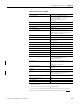
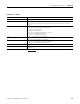
Analog I/O Module Specifications Appendix A
Thermocouples B, E, J, K, R, S, T, N, C
Current draw @ 5.1V 250 mA
Current draw @ 24V 125 mA
Power dissipation, max 4.3 W
Thermal dissipation 14.66 BTU/hr
Input impedance >10 MΩ
Open circuit detection time Positive full scale reading within 2 s
Overvoltage protection, max 120V AC/DC
Normal mode noise rejection
60 dB at 60 Hz
(1)
Common mode noise rejection 120 dB @ 60 Hz
100 dB @ 50 Hz
Channel bandwidth
15 Hz (-3 dB)
(1)
Settling time
<80 ms to 5% of full scale
(1)
Calibrated accuracy @ 25 °C Better than 0.1% of range
Calibration interval 6 months
Local CJC sensor accuracy ±0.3…3.2 °C, depending on channel
Remote CJC sensor accuracy ±0.3 °C
Offset drift 0.5 μV/°C
Gain drift with temperature 65 ppm/°C, 80 ppm/°C max
Module error 0.5% of range
Module scan time 25 ms min floating point (millivolt)
50 ms min floating point (temperature)
10 ms min integer (millivolt)
(1)
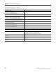
Isolation voltage 250V (continuous), basic insulation type, input channels
to backplane, and input channel to channel
Routine tested at 1350V AC for 2 s
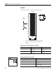
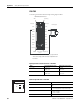
Removable terminal block 1756-TBNH
1756-TBSH
Slot width 1
Wire size
0.33… 2.1 mm
2
(22…14 AWG) solid or stranded copper
wire rated at 90 °C (194 °F), or greater, 1.2 mm
(0.047 in.) insulation max
(2)
Wire category
2
(3)
North American temperature code T4A
IEC temperature code T4
Enclosure type None (open-style)
(1)
Notch filter dependent.
(2)
Maximum wire size requires extended housing, catalog number 1756-TBE.
(3)
Use this conductor category information for planning conductor routing as described in the system-level
installation manual. See the Industrial Automation Wiring and Grounding Guidelines, publication 1770-4.1.
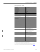
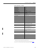
Technical Specifications - 1756-IT6I
Attribute 1756-IT6I