
Manual

294 Publication 1756-UM009C-EN-P - December 2010
Appendix A Analog I/O Module Specifications
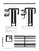
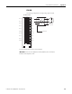
1756-IF16
ControlLogix voltage/current analog input module
12
34
56
78
910
1112
1314
1516
1718
1920
2122
2324
2526
2728
2930
3132
3334
3536
Shield
Ground
Channel 0
Channel 3
Jumper
Wires
i
i
A
2-wire
Transm itte r
A
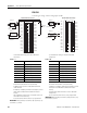
1756-IF16 Differential Current
IN-0
IN-1
IN-2
IN-3
IN-7
RTN
IN-4
IN-5
IN-6
IN-15
IN-8
IN-9
IN-10
IN-11
RTN
IN-12
IN-13
IN-14
i RTN-0
i RTN-1
i RTN-2
i RTN-3
i RTN-7
RTN
i RTN-4
i RTN-5
i RTN-6
i RTN-15
i RTN-8
i RTN-9
i RTN-10
i RTN-11
RTN
i RTN-12
i RTN-13
i RTN-14
12
34
56
78
910
1112
1314
1516
1718
1920
2122
2324
2526
2728
2930
3132
3334
3536
+
–
+
–
Shield Ground
Channel 0
Channel 3
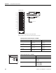
1756-IF16 Differential Voltage
IN-0
IN-1
IN-2
IN-3
IN-7
RTN
IN-4
IN-5
IN-6
IN-15
IN-8
IN-9
IN-10
IN-11
RTN
IN-12
IN-13
IN-14
i RTN-0
i RTN-1
i RTN-2
i RTN-3
i RTN-7
RTN
i RTN-4
i RTN-5
i RTN-6
i RTN-15
i RTN-8
i RTN-9
i RTN-10
i RTN-11
RTN
i RTN-12
i RTN-13
i RTN-14
Shield Ground
· Use this table when wiring your module in differential
current mode.
· All terminals marked RTN are connected internally.
· A 249 Ω current loop resistor is located between IN-x and
iRTN-x terminals.
· If multiple (+) or multiple (-) terminals are tied together, connect
that tie point to a RTN terminal to maintain the module’s
accuracy.
· Place additional loop devices (such as strip chart recorders) at
the A location in the current loop.
· Do not connect more than two wires to any single terminal.
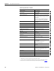
IMPORTANT: When operating in four-channel, High-speed mode, only
use channels 0, 2, 4 and 6.
Table 1.A
This channel Uses these terminals
Channel 0 IN-0 (+), IN-1 (-), i RTN-0
Channel 1 IN-2 (+), IN-3 (-), i RTN-2
Channel 2 IN-4 (+), IN-5 (-), i RTN-4
Channel 3 IN-6 (+), IN-7 (-), i RTN-6
Channel 4 IN-8 (+), IN-9 (-), i RTN-8
Channel 5 IN-10 (+), IN-11 (-), i RTN-10
Channel 6 IN-12 (+), IN-13 (-), i RTN-12
Channel 7 IN-14 (+), IN-15 (-), i RTN-14
· Use this table when wiring your module in differential
voltage mode.
· All terminals marked RTN are connected internally.
· If multiple (+) or multiple (-) terminals are tied together, connect
that tie point to a RTN terminal to maintain the module’s
accuracy.
· Terminals marked RTN or i RTN are not used for differential
voltage wiring.
· Do not connect more than two wires to any single terminal.
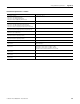
IMPORTANT: When operating in four-channel, High-speed mode, only
use channels 0, 2, 4 and 6.
Table 1.B
This channel Uses these terminals
Channel 0 IN-0 (+), IN-1 (-)
Channel 1 IN-2 (+), IN-3 (-)
Channel 2 IN-4 (+), IN-5 (-)
Channel 3 IN-6 (+), IN-7 (-)
Channel 4 IN-8 (+), IN-9 (-)
Channel 5 IN-10 (+), IN-11 (-)
Channel 6 IN-12 (+), IN-13 (-)
Channel 7 IN-14 (+), IN-15 (-)
User-provided
Loop Power