
Manual

290 Publication 1756-UM009C-EN-P - December 2010
Appendix A Analog I/O Module Specifications
12
34
56
78
910
1112
1314
1516
1718
1920
2122
2324
2526
2728
2930
3132
3334
3536
i
i
A
Shield Ground
Channel 0
Channel 5
Jumper
Wires
2-wire
Transmitter
IN-0
IN-1
IN-2
IN-3
IN-7
RTN
IN-4
IN-5
IN-6
Not Used
Not Used
Not Used
Not Used
Not Used
Not Used
Not Used
Not Used
Not Used
i RTN-0
i RTN-1
i RTN-2
i RTN-3
i RTN-7
RTN
i RTN-4
i RTN-5
i RTN-6
Not Used
Not Used
Not Used
Not Used
Not Used
Not Used
Not Used
Not Used
Not Used
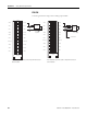
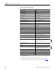
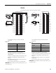
1756-IF8 Single-ended Cur rent
12
34
56
78
910
1112
1314
1516
1718
1920
2122
2324
2526
2728
2930
3132
3334
3536
+
–
+
–
IN-0
IN-1
IN-2
IN-3
IN-7
RTN
IN-4
IN-5
IN-6
Not Used
Not Used
Not Used
Not Used
Not Used
Not Used
Not Used
Not Used
Not Used
i RTN-0
i RTN-1
i RTN-2
i RTN-3
i RTN-7
RTN
i RTN-4
i RTN-5
i RTN-6
Not Used
Not Used
Not Used
Not Used
Not Used
Not Used
Not Used
Not Used
Not Used
Shield Ground
Channel 0
Channel 1
Shield Ground
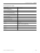
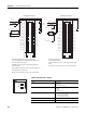
1756-IF8 Single-ended Voltage
· All terminals marked RTN are connected internally.
· For current applications, all terminals marked iRTN must be
wired to terminals marked RTN.
· A 249 Ω current loop resistor is located between IN-x and
iRTN-x terminals.
· Place additional loop devices (such as strip chart recorders) at
the A location in the current loop.
· Do not connect more than two wires to any single terminal.
· All terminals marked RTN
are connected internally.
· Terminals marked i RTN are not used for single-ended voltage
wiring.
· Do not connect more than two wires to any single terminal.
User-provided
Loop Power
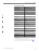
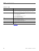
Technical Specifications - 1756-IF8
Attribute 1756-IF8
Inputs 8 single-ended
4 differential
2 high-speed differential
Input range ±10.25V
0...10.25V
0...5.125V
0…20.5 mA
Resolution ±10.25V: 320 μV/cnt (15 bits plus sign bipolar)
0…10.25V: 160 μV/cnt (16 bits)
0…5.125V: 80 μ/V cnt (16 bits)
0…20.5mA: 0.32 μA/cnt (16 bits)
Current draw @ 5.1V 150 mA
Current draw @ 24V 40 mA
ANALOG INPUT
CAL
OK