
Manual

280 Publication 1756-UM009C-EN-P - December 2010
Appendix A Analog I/O Module Specifications
+
–
1
2
3
4
56
78
910
1112
1314
1516
1718
1920
VOUT-1
IN-1/I
RTN-1
VOUT-3
IN-3/I
RTN-3
Not Used
VOUT-5
IN-5/I
RTN-5
VOUT-0
IN-0/I
RTN-0
VOUT-2
IN-2/I
RTN-2
Not Used
VOUT-4
IN-4/I
RTN-4
4-wire
Transmitter
24V DC
Shield Ground
+
–
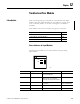
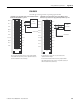
1756-IF6CIS 4-wire Transmitter Connected to the Module and an
External, User-provided Power Supply Providing 24V DC Loop Power
· If separate power sources are used, do not exceed the
specified isolation voltage.
· Do not connect more than two wires to any single terminal.
· Place additional loop devices (such as strip chart recorders) at
either A location in the current loop.
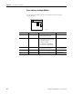
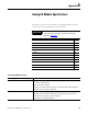
Input Signal to User Count Conversion - 1756-IF6CIS
Range Low Signal and User Counts High Signal and User Counts
0…20 mA 0 mA
-32768 counts
21.09376 mA
32767 counts
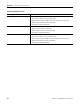
Technical Specifications - 1756-IF6CIS
Attribute 1756-IF6CIS
Inputs 6 individually isolated current sourcing
Input range 0…21 mA
Resolution 16 bits
0.34 μA/bit
Current draw @ 5.1V 250 mA
Current draw @ 24V 275 mA
Power dissipation, max 5.1 W @ 60 °C (140 °F)
Thermal dissipation 17.4 BTU/hr
Input impedance 215 Ω, approx
Sourcing voltage, min 20V DC
Sourcing voltage, max 30V DC
Sourcing current, max Current limited to <30 mA
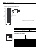
ANALOG INPUT
CAL
OK