
Manual

Publication 1756-UM009C-EN-P - December 2010 213
Configure ControlLogix Analog I/O Modules Chapter 10
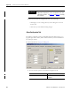
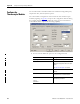
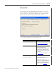
2. After the channels are configured, do one of the following:
• Click Apply to store a change but stay on the dialog box to choose
another tab.
• Click OK to apply the change and close the dialog box.
• Click Cancel to close the dialog box without applying changes.
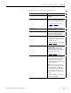
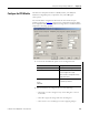
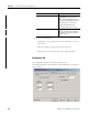
Process Alarms
(1)
High High
High
Low
Low Low
Type a value for each of the four alarm
trigger points that alert you when the
module has exceeded these limitations.
You also can use the respective slider
icon to set a trigger value.
The Unlatch buttons are enabled only
when the module is online.
Disable All Alarms Check the box to disable all alarms.
Important: When you disable all
alarms, you disable process, rate, and
channel diagnostic alarms (for example,
underrange and overrange).
We recommend that you disable only
unused channels so extraneous alarm
bits are not set.
Latch Process Alarms Check the box to latch an alarm in the
set position even if the condition that
causes the alarm disappears.
Latch Rate Alarms Check the box if the rate of change
between input samples exceeds the
trigger point for the channel.
See
page 64
in
Chapter 4
for a sample
rate of change formula.
Deadband Type a deadband value that works with
the process alarms. The deadband
gauges the input data to set or remove
an alarm for a process alarm.
See an alarm deadband chart on
page 63
in
Chapter 4
.
Rate Alarm
(2)
Type a value used to determine the rate
of change to trigger a rate alarm.
(1)
Process alarms are not available in integer mode or in applications by using the 1756-IF16 module in
the single-ended, floating point mode. The values for each limit are entered in scaled
engineering units.
(2)
Rate alarms are not available in integer mode or in applications by using the 1756-IF16 module in the
single-ended, floating point mode. The values for each limit are entered in scaled
engineering units.
Field Name Description