
Manual

Publication 1756-UM009C-EN-P - December 2010 211
Configure ControlLogix Analog I/O Modules Chapter 10
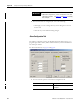
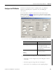
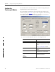
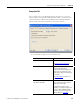
1. Choose from the options on the Configuration tab.
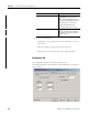
Field Name Description
Channel Click the channel that is being
configured.
Input Range Choose the module’s input range to
determine the minimum and maximum
signals that are detected by the module.
See .
page 49
in
Chapter 3
for a chart
showing range and resolution
per module.
Sensor Offset Type a value to compensate for any
sensor offset errors.
Notch Filter Use the default (60 Hz) or choose a
frequency that attenuates the input
signal at this specified frequency.
Digital Filter Choose a value in milliseconds that
specifies the time constant for a digital
first order lag filter on the input. A value
of 0 disables the filter.
See
page 62
in
Chapter 4
for an amplitude
chart example.
Scaling You can scale only with the floating
point data format. Scaling lets you
configure two points in the module’s
operating range with the associated low
and high points for this range.
See
page 50
in
Chapter 3
for details.
RTS Choose a value in milliseconds that the
module performs a Real Time Sample
(RTS). This parameter determines when
the module scans all input channels,
stores data into memory, and multicasts
the update channel data.
Note: If the RTS value is less than or
equal to the RPI, each multicast of data
from the module will have updated
channel information. If the RTS value is
greater than the RPI, the module
multicats at both the RTS value and the
RPI rate.
The module resets the RPI timer each
time an RTS is performed.