
Manual

180 Publication 1756-UM009C-EN-P - December 2010
Chapter 8 Isolated Analog Output Modules (1756-OF6CI and 1756-OF6VI)
Fault Reporting in Floating
Point Mode
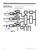
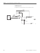
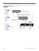
The illustration offers an overview of the fault reporting process in floating
point mode.
15 14 13 12 11
543210
54321076
15 = AnalogGroupFault
13 = OutGroupFault
12 = Calibrating
11 = Cal Fault
14 is not used by the
OF6CI or OF6VI
5 = Ch5Fault
4 = Ch4Fault
3 = Ch3Fault
2 = Ch2Fault
1 = Ch1Fault
0 = Ch0Fault
5 = ChxNotANumber
4 = ChxCalFault
3 = ChxInHold
2 = ChxRampAlarm
1 = ChxLLimitAlarm
0 = ChxHLimitAlarm
Not a Number, Output in Hold, and Ramp
Alarm conditions do not set additional
bits. You must monitor them here.
Low and High Limit Alarm
conditions set the
appropriate bits in the
Channel Fault word.
7 & 6 are not used by
OF6CI or OF6VI
If set, any bit in the Channel Fault word, also sets the Analog
Group Fault and Output Group Fault in the Module Fault word.
A channel calibration fault
sets the calibration fault in
the Module Fault word.
When the module is calibrating, all
bits in the Channel Fault word are set.
Module Fault Word
(described on
page 181
)
Channel Fault Word
(described on
page 181
)
Channel Status Words
(one for each channel–
described ion
page 182
)
41343