
Manual

158 Publication 1756-UM009C-EN-P - December 2010
Chapter 7 Non-isolated Analog Output Modules (1756-OF4 and 1756-OF8)
Wire the 1756-OF8 Module
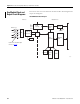
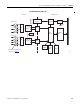
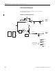
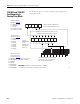
The illustration shows wiring examples for the 1756-OF8 module.
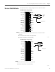
1756-OF8 Current wiring example
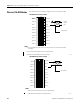
1756-OF8 Voltage wiring example
VOUT-2
IOUT-2
RTN
VOUT-3
IOUT-3
VOUT-0
IOUT-0
RTN
VOUT-1
IOUT-1
12
34
5
6
7
8
910
11
12
1314
1516
1718
19
20
VOUT-6
IOUT-6
RTN
VOUT-7
IOUT-7
VOUT-4
IOUT-4
RTN
VOUT-5
IOUT-5
i
A
NOTES:
1. Place additional loop devices (that is, strip chart recorders, and so forth) at the A location
noted above.
2. Do not connect more than two wires to any single terminal.
3. All terminals marked RTN are connected internally.
Current
output
load
Shield ground
40916-M
VOUT-4
VOUT-2
IOUT-2
RTN
VOUT-3
IOUT-3
VOUT-0
IOUT-0
RTN
VOUT-1
IOUT-1
12
34
5
6
7
8
910
11
12
1314
1516
1718
19
20
VOUT-6
IOUT-6
RTN
VOUT-7
IOUT-7
VOUT-4
IOUT-4
RTN
VOUT-5
IOUT-5
+
–
NOTES:
1. Do not connect more than two wires to any single terminal.
2. All terminals marked RTN are connected internally.
40917-M
Shield ground