
Manual

154 Publication 1756-UM009C-EN-P - December 2010
Chapter 7 Non-isolated Analog Output Modules (1756-OF4 and 1756-OF8)
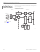
Use Module Block and
Output Circuit Diagrams
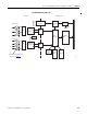
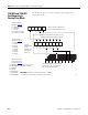
This section shows the 1756-OF4 and 1756-OF8 modules’ block diagrams and
output circuit diagrams.
1756-OF4 Module Block Diagram
DC-DC
Converter
16-bit D/A
Converter
RIUP
Circuit
43510
Vref
Optos
Micro-
controller
Serial
EEPROM
FLASH
ROM
SRAM
System
+5V
Field Side Backplane Side
DC-DC
Shutdown
Circuit
Channels 0 - 3
Details of the 1756-OF8 output
circuitry on
page 156
.
Mux
Backplane
ASIC