
Manual

Publication 1756-UM009C-EN-P - December 2010 153
Non-isolated Analog Output Modules (1756-OF4 and 1756-OF8) Chapter 7
Clamp/Limit Alarms
This function works directly with clamping. When a module receives a data
value from the controller that exceeds clamping limits, it applies signal values
to the clamping limit but also sends a status bit to the controller notifying it
that the value sent exceeds the clamping limits.
Using the example above, if a module has clamping limits of 8V and -8V but
then receives data to apply 9V, only 8V is applied to the screw terminals and
the module sends a status bit back to the controller informing it that the 9V
value exceeds the module’s clamping limits.
To see how to enable all alarms, see
page 223
.
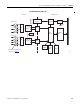
Data Echo
Data Echo automatically multicasts channel data values that match the analog
value that was sent to the module’s screw terminals at that time.
Fault and status data is also sent. This data is sent in the format (floating point
or integer) selected at the requested packet interval (RPI).
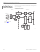
User Count Conversion to Output Signal
User counts can be computed in Integer mode for the 1756-OF4 and
1756-OF8 modules.
The straight line formulas that can be used to calculate or program a
Compute (CPT) instruction are shown in the table.
For example, if you have 6 mA in the 0…20 mV range, the
user counts = -14300. Counts = 6281 for 2 V in the
+/-10V range.
For a table with related values, refer to ControlLogix 1756-OF4
and 1756-OF8 User Count Conversion to Output Signal, Knowledgebase
Technical Note ID 41570.
IMPORTANT
Limit alarms are available only in floating point mode.
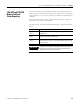
Available Range User Count Formula
O…20 mA y = 3077.9744124443446x-32768
where y = counts; x = mA
+/-10V y = 3140.5746817972704x-0.5
where y = counts; x = V