ControlLogix SynchLink Module 1756-SYNCH User Manual
Important User Information Solid state equipment has operational characteristics differing from those of electromechanical equipment. Safety Guidelines for the Application, Installation and Maintenance of Solid State Controls (Publication SGI-1.1 available from your local Rockwell Automation sales office or online at http://www.ab.com/manuals/gi) describes some important differences between solid state equipment and hard-wired electromechanical devices.
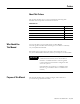
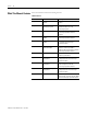
Summary of Changes Introduction This release of this publication contains updated information. Change bars, as shown in the right margin of this page, designate locations in the publication that contain changed information. New and Revised Information Table Summary of Changes.1 lists the new and revised information included in this publication. Table Summary of Changes.
Summary of Changes 2 Publication 1756-UM521C-EN-P - July 2004
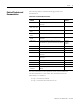
Preface About This Preface This preface describes how to use this manual. The following table describes what this preface contains and its location. Table Preface.
Preface 2 Using the Latest Module Firmware This manual describes changes to the 1756-SYNCH module when the module uses firmware revision 2.18. Some of the features described in this publication may not be available on modules using previous firmware revisions. We recommend that you upgrade your 1756-SYNCH module to firmware revision 2.18 or greater when possible to use fully the module’s functionality.
Preface 3 5. Expand the network until you see the module. If the required network is not shown, first configure a driver for the network in RSLinx software. 6. Select the controller and choose OK. 7. Select the revision level to which you want to update the 1756-SYNCH module and choose Next >. IMPORTANT If the Revision list is empty, download a new upgrade kit. Some older upgrade kits do not work with new modules. 8. To start the update of the module, choose Finish and then Yes.
Preface 4 What This Manual Contains This user manual contains the following sections: Table Preface.
Preface Related Products and Documentation 5 The following table lists related ControlLogix products and documentation: Table Preface.3 Related Documentation Catalog number: Document title: Publication number: 1756-SYNCH ControlLogix SynchLink Module Installation Instructions 1756-IN575 1756-A4, -A7, -A10, -A13, -A17 ControlLogix Chassis Installation Instructions 1756-IN080 1756-PA72, -PB72 ControlLogix Power Supply Installation Instructions 1756-5.
Preface 6 Notes: Publication 1756-UM521C-EN-P - July 2004
Table of Contents Chapter 1 What is the 1756-SYNCH module? What is the ControlLogix SynchLink Module?. . . . . . . . . . . . . . . . . . 1-1 What Data Does the SynchLink Module Transfer? . . . . . . . . . . . Why Synchronize Time Between Chassis? . . . . . . . . . . . . . . . . . . What Are Some of the Features Available On the ControlLogix SynchLink Module? . . . . . . . . . . . . . . . . . . . . . . . . Connecting a SynchLink Module to a SynchLink System . . . . . . . . .
Table of Contents 2 Chapter 4 Installing the SynchLink Module Noting the Power Requirements . . . . . . . . . . . . . . . . . . . . . . . . . . . . . Installing the Module . . . . . . . . . . . . . . . . . . . . . . . . . . . . . . . . . . . . . . Connecting the Fiber Optic Cable . . . . . . . . . . . . . . . . . . . . . . . . . . . Removing the Module . . . . . . . . . . . . . . . . . . . . . . . . . . . . . . . . . . . . . Chapter Summary and What’s Next . . . . . . . . . . . . . . . . . . . . . . . .
Table of Contents 3 Appendix B Configuring the Star Configuration Using Remote Axis Control. . . . . . . . . . . . . . . . . . . . . . . . . . . . . . . . . B-2 Configure Time Master Chassis - Master Node . . . . . . . . . . . . . . B-2 Configure Time Slave Chassis - End Node . . . . . . . . . . . . . . . . . B-8 Configure Time Slave Chassis - End Node . . . . . . . . . . . . . . . . B-13 Appendix C Configuring the Daisy Chain Configuration Configure Time Master Chassis - Master Node . . . . . . . . . .
Table of Contents 4 Publication 1756-UM521C-EN-P - July 2004
Chapter 1 What is the 1756-SYNCH module? This chapter describes the ControlLogix SynchLink module. It also describes what you must know and do before using the SynchLink module. Table 1.
1-2 What is the 1756-SYNCH module? Why Synchronize Time Between Chassis? In synchronizing time between chassis, the SynchLink module allows you to: • share motion data from chassis to chassis because a consistent time reference is available among chassis for interpolation of velocity and position data. • timestamp I/O in multiple chassis and have a common time reference with which to compare the timestamps.
What is the 1756-SYNCH module? Connecting a SynchLink Module to a SynchLink System 1-3 ControlLogix SynchLink modules mount in a ControlLogix chassis and connects to other SynchLink node through a fiber optic cable system. For more information on the available fiber optic cables, see Table 1.2. Table 1.2 Fiber Optic Cables Available with the 1756-SYNCH Module Catalog number: Cable length 1403-CF001 1m (3.28ft) 1403-CF003 3m (9.84ft) 1403-CF005 5m (16.4ft) 1403-CF010 10m (32.
1-4 What is the 1756-SYNCH module? Physical Features of the ControlLogix SynchLink Module Figure 1.1 Module side view Module front view LINK COMM LINK SYNC OK Backplane Connector- Interface to the ControlLogix system backplane Status Indicators 42744 Transmit Fiber Port Receive Fiber Port Table 1.4 lists descriptions of the physical features shown in Figure 1.1. Table 1.
What is the 1756-SYNCH module? Using Module Identification and Status Information 1-5 Each ControlLogix SynchLink module maintains specific identification information that separates it from all other modules. This information assists you in tracking all the components of your system. For example, you can track module identification information to be aware of exactly what modules are located in any ControlLogix rack at any time. While retrieving module identity, you can also retrieve the module’s status.
1-6 What is the 1756-SYNCH module? Preventing Electrostatic Discharge This module is sensitive to electrostatic discharge. ATTENTION This equipment is sensitive to electrostatic discharge, which can cause internal damage and affect normal operation. Follow these guidelines when you handle this equipment: • Touch a grounded object to discharge potential static. • Wear an approved grounding wriststrap. • Do not touch connectors or pins on component boards.
Chapter 2 Time Synchronization in the ControlLogix System This chapter describes how the ControlLogix SynchLink module fits in the ControlLogix system. Table 2.
2-2 Time Synchronization in the ControlLogix System Using the Coordinated System Time (CST) The Coordinated System Time (CST) is the clocking mechanism used to achieve time synchronization in a ControlLogix chassis. The ControlLogix Coordinated System Time (CST) clock is a 64-bit clock on the backplane of the ControlLogix chassis. It has a 1μS resolution and is used as the main time reference for all modules plugged into a chassis backplane.
Time Synchronization in the ControlLogix System 2-3 Multiple Rockwell Automation products can be synchronized with SynchLink. In addition to the SynchLink module, the PowerFlex 700S and the 1756-DMxxx series products (both used for drive control) also use SynchLink to achieve drive to drive synchronization.
2-4 Time Synchronization in the ControlLogix System System Synchronization When a SynchLink system is initialized, the individual SynchLink nodes power-up at separate times and the individual SynchLink node clocks begin to count at arbitrary points in time. When this occurs, the system is not yet synchronized. As the master node clock counts, it reaches a point where it rolls over and goes back to zero.
Time Synchronization in the ControlLogix System How Do the CST Clock and SynchLink Node Clock Work Together? 2-5 As stated earlier, the ControlLogix Coordinated System Time clock (CST) is a 64-bit clock on the ControlLogix backplane. It is used as the main time reference for all modules plugged into a ControlLogix chassis. The SynchLink node clock is used to establish the time reference on the SynchLink fiber. Figure 2.
2-6 Time Synchronization in the ControlLogix System SynchLink communications are a unidirectional data transfer from one SynchLink node to another. Each configuration starts with a single Master Node. The SynchLink network can be configured in the following ways. What are the SynchLink Configurations? • Star Configuration • Daisy Chain Configuration • Ring Configuration Do not mix the configurations (i.e. begin in the star configuration and change to the daisy chain configuration).
Time Synchronization in the ControlLogix System 2-7 Daisy Chain Configuration In the daisy chain configuration, the SynchLink network starts at the Master Node and ends at an End Node. You can include Center Nodes (shown in Figure ) in the configuration as needed. Figure 2.6 Master Node SynchLink Center Node Center Node End Node ControlNet 42746 IMPORTANT In the daisy chain configuration, you can use a maximum of 10 nodes, including the master and end nodes.
2-8 Time Synchronization in the ControlLogix System Ring Configuration The ring configuration is a permutation of the daisy chain configuration. In the ring chain configuration, the SynchLink network starts and ends at the Master Node. You can include Center Nodes (shown in Figure ) in the configuration as needed. Master Node SynchLink Center Node Center Node Center Node ControlNet 42748 IMPORTANT In the ring chain configuration, you can use a maximum of 10 nodes.
Chapter 3 SynchLink Module Features This chapter describes the ControlLogix SynchLink module features. Table 3.
3-2 SynchLink Module Features Module Features That Cannot Be Configured These general module features (e.g. Removal and Insertion Under Power) are supported on the module regardless of configuration and application.
SynchLink Module Features 3-3 Repeated electrical arcing causes excessive wear to contacts on both the module and its mating connector. Worn contacts may create electrical resistance that can affect module operation. Module Fault Reporting ControlLogix SynchLink modules provide both hardware and software indication when a module fault has occurred. Each module’s LED fault indicator and RSLogix 5000 will graphically display this fault and include a fault message describing the nature of the fault.
3-4 SynchLink Module Features Status Indicator (LED) Information The ControlLogix SynchLink module has status indicators (LED) on the front of the module that allow you to check the module health and operational status. With the LED indicators, you can check: • SynchLink and ControlLogix backplane status • Module health status For examples of LED indicators, see page 6-1.
SynchLink Module Features 3-5 Use Last Configuration When Connection to Owner-Controller Closes - For Module’s Using Firmware Revision 2.18 or Greater With firmware revision 2.18 or greater, the 1756-SYNCH module can continue to operate, using its last configuration, when the module’s connection to the owner-controller closes. Table 3.2 If the 1756-SYNCH module is used in this scenario: • The 1756-SYNCH module is located in a chassis with two ControlLogix controllers.
3-6 SynchLink Module Features transferred between them). The SynchLink module can receive and transmit data and, therefore, uses a Receive Port Communications Format and Transmit Port Communications Format. SynchLink messages are structured as six 32-bit words; the words are divided into three types as described in Table 3.3: Table 3.3 Word Type: Description: Direct Data delivered in a single message. A SynchLink message can contain a maximum of four direct data words; each word is 32 bits in length.
SynchLink Module Features 3-7 Multiple Port Communications Formats in Single Module You must set a communications format for receiving data (Receive Port Communications Format) and transmitting data (Transmit Port Communications Format) in each SynchLink module. The following requirements apply to communication format choices: • If a SynchLink module does not receive data (e.g.
3-8 SynchLink Module Features Module-Defined Data Tags When you create a module, RSLogix 5000 creates module-defined data types and tags. These tags allow you to access the Configuration, Input and Output Data of the module via the controller’s ladder logic. The types of tags created vary, depending on which communications format you choose when creating a module.
SynchLink Module Features 3-9 The SynchLink module updates its receive and transmit buffers once every 500μS. Because direct data can be passed through from node to node once every 50μS, up to 10 nodes can be updated with direct data in a single 500μS SynchLink scan. Pass-through functionality only applies to direct data in a daisy chain configuration, though; axis data and buffered data cannot be passed through.
3-10 SynchLink Module Features Table 3.
SynchLink Module Features 3-11 Electronic Keying Instead of plastic mechanical backplane keys, electronic keying allows the ControlLogix system to control what modules belong in the various slots of a configured system. During module configuration, you must choose one of the following keying options for your 1756-SYNCH module: • Exact Match • Compatible Match • Disable Keying When the controller attempts to connect to and configure a 1756-SYNCH module (e.g.
3-12 SynchLink Module Features Table 3.6 describes the keying options available with your 1756-SYNCH module. Table 3.6 Keying option: Definiton: Exact Match All of the parameters listed above must match or the inserted module will reject a connection to the controller. Compatible Match The Compatible Match mode allows a 1756-SYNCH module to determine whether it can emulate the module defined in the configuration sent from the controller.
SynchLink Module Features 3-13 The Electronic Keying feature is configured on the following screen. Electronic Keying Requested Packet Interval The Requested Packet Interval (RPI) is a configurable parameter that defines when the module multicasts its data onto the local chassis backplane. In the SynchLink module, though, the RPI’s role is dictated by the data the SynchLink transfers. Axis Data The RPI does not have an effect on produced or consumed axis data.
3-14 SynchLink Module Features Buffered, Direct and Diagnostic Data - RPI Effect on Input Data (to the controller) The RPI is one of two mechanisms available through the 1756-SYNCH module to update the module’s input data onto the backplane. Input data is transferred from the SynchLink module to its owner-controller at the rate defined in the RPI.
SynchLink Module Features 3-15 SynchLink Transmitted Axes Most applications using the ControlLogix SynchLink module use it for Remote Axis Control. You can use the SynchLink module to produce axes from a master chassis and broadcast the data to other chassis. The module can produce and consume two axes (i.e. Axis 0 & Axis 1). Slave chassis consume the broadcast axis data and redistribute it to their local motion planners (i.e. the Logix controller in their local chassis).
3-16 SynchLink Module Features Transmitted Direct Words The SynchLink module can transmit data from the following direct word sources: • Output Direct Words (0-3) • Received Direct Words (0-3) • Multiplier In initial configuration, you can choose the Transmitted Direct Words, but you must use ladder logic to move data to those locations in data type tags. For more information on the data tags, see Appendix E. Direct Words Direct words are data delivered in a single message.
SynchLink Module Features 3-17 The multiplier can only transmit the same word it received (i.e. this feature does not allow your module to receive direct word 0 and transmit it as direct word 1). The multiplier output is limited to 16 bits; any value generated by the multipler larger than 65535 is truncated to 16 bits, and a multiplier overflow error (described below) is reported by the Synchlink module.
3-18 SynchLink Module Features CST and SynchLink Mastership The SynchLink module can be configured for multiple mastership and slave roles in respect to the Coordinated System Time and the SynchLink. Table 3.7 describes the ways you can configure your 1756-SYNCH module’s role in CST Mastership. Table 3.7 Possible SynchLink Configurations This configuration: Only the Make SynchLink CST Master box is checked. Means: • This module relays time from the Chassis CST Master to the SynchLink.
SynchLink Module Features 3-19 Table 3.7 Possible SynchLink Configurations This configuration: Means: Dependence on SynchLink is Not Required • The module is a Time Slave on SynchLink. • The module is the CST Time Master of the local chassis. • You MUST have selected another module on the fiber optic cable to be the SynchLink CST Master. • If your 1756-SYNCH module uses firmware revision 2.
3-20 SynchLink Module Features Chapter Summary and What’s Next Publication 1756-UM521C-EN-P - July 2004 In this chapter, you read about the ControlLogix SynchLink module features. For information about Installing the SynchLink Module, see Chapter 4.
Chapter 4 Installing the SynchLink Module This chapter describes how to install the ControlLogix SynchLink module. Table 4.1 For information on: See page: Noting the Power Requirements 4-1 Installing the Module 4-2 Connecting the Fiber Optic Cable 4-3 Removing the Module 4-4 IMPORTANT Before you install and use your module you should have already installed and grounded a 1756 chassis and power supply.
4-2 Installing the SynchLink Module Installing the Module You can install or remove the module while chassis power is applied. WARNING When you insert or remove the module while backplane power is on, an electrical arc can occur. This could cause an explosion in hazardous location installations. Be sure that power is removed or the area is nonhazardous before proceeding. Repeated electrical arcing causes excessive wear to contacts on both the module and its mating connector.
Installing the SynchLink Module Connecting the Fiber Optic Cable 4-3 Your 1756-SYNCH module has two ports for fiber optic cables. The front port receives data, and the rear port transmits data. 1. Remove the plugs from the ports at the bottom of the module. TIP Keep the plugs that were removed to connect the fiber optic cables. When the cables are disconnected, you can reinsert the plugs to protect the ports. 2. Connect the fiber optic cables as shown below. Figure 4.
4-4 Installing the SynchLink Module Removing the Module ATTENTION Before you remove the module, you must disconnect the fiber optic cables. 1. Pull the fiber optic cable out of the connection port. TIP If you kept the plugs that were removed to connect the fiber optic cables, reinsert them to protect the ports. 2. Push in the top and bottom locking tabs. 3. Pull the module out of the chassis as shown. Figure 4.
Chapter 5 Configuring the SynchLink Module This chapter describes how to configure the ControlLogix SynchLink module using RSLogix 5000. Table 5.1 For information on: See page: Overview of the Configuration Process 5-2 Choose a SynchLink Configuration 5-3 Creating a New Module 5-4 Downloading New Configuration Data 5-8 Changing Configuration After Module Operation Has Begun 5-9 You must configure your module upon installation. The module will not work until it has been configured.
5-2 Configuring the SynchLink Module Overview of the Configuration Process Figure 5.1 shows an overview of the configuration process: Figure 5.1 1. Choose a SynchLink configuration. Star Configuration Daisy Chain Configuration Ring Configuration 2. Create a new RSLogix 5000 project. Steps 2 - 5 must be taken for every SynchLink module (and its respective chassis) in the chosen SynchLink configuration. These configuration changes occur before module operation begins. 3.
Configuring the SynchLink Module Choose a SynchLink Configuration 5-3 You must use one of the following SynchLink configurations: Star Configuration - See Appendix B for an example. Figure 5.2 ControlNet SynchLink Hub Hub Hub 42747 Daisy Chain Configuration - See Appendix for an example. Figure 5.3 SynchLink ControlNet 42746 Ring Configuration - See Appendix D for an example. Figure 5.
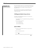
5-4 Configuring the SynchLink Module Creating a New Module After you have started RSLogix 5000 and created a processor, you must create a new module. The wizard allows you to create a new module and configure it. IMPORTANT You must be offline when you create a new module. 1. If your application is online, go offline. A. Click on the triangle to see the pull-down menu. B. Click on Go Offline. 2. Access the Select Module Type screen. A. Right-click on I/O Configuration. B. Select New Module.
Configuring the SynchLink Module 5-5 3. Select the module type. B. Make sure the Major Revision number matches the label on the side of your module A. Select a module. C. Select a module. 4. Begin configuration on the naming screen. A. Name the module. E. Set your module’s slot. B. Type a description (optional). F. Choose an Electronic Keying method. A detailed explanation of this field is provided on the next page 3-11. C. Choose a Communications Format for the receive and transmit ports.
5-6 Configuring the SynchLink Module 5. When you click on Next, you see the series of wizard screens that enable you to configure the module. Although each screen maintains importance during online monitoring, some of the screens that appear during this initial module configuration process are blank. They are not shown here.
Configuring the SynchLink Module 5-7 Use the pull-down menus to choose which direct words are transmitted. Click here to move to the next page Set the 1756-SYNCH module’s role in Coordinated System Time (CST) Mastership. For more information on Time Mastership, see CST and SynchLink Mastership on page 3-18. Click here to finish configuration.
5-8 Configuring the SynchLink Module Downloading New Configuration Data After you have changed the configuration data for a module, the change does not actually take affect until you download the new program which contains that information. This downloads the entire program to the controller overwriting any existing programs. Pull down this menu and click here to download the new data RSLogix 5000 verifies the download process with this pop-up screen.
Configuring the SynchLink Module Changing Configuration After Module Operation Has Begun 5-9 You change configuration for your SynchLink module after operation has begun, but you must go offline first. Follow these steps to change the SynchLink module configuration: 1. Go offline. A. Click on the triangle to see the pull-down menu. B. Click on Go Offline. 2. Access the module properties in RSLogix 5000. A. Right-click on the module to see the pull-down menu. B. Click on Properties.
5-10 Configuring the SynchLink Module 3. Make the necessary changes. A. In this example, the Connection tab was accessed to change the RPI. B. Click on OK to make the changes.. After you make your configuration changes, you must download the new configuration, as described on page 5-8. Chapter Summary and What’s Next In this chapter, you read about the general configuration process.
Chapter 6 Troubleshooting the SynchLink Module This chapter describes how to troubleshoot the ControlLogix SynchLink module. Table 6.1 For information on: Using the Status Indicators See page: Using the Status Indicators 6-1 Using RSLogix 5000 to Troubleshoot the Module 6-3 The SynchLink module uses status indicators to show SynchLink and communications status (red/green) and a bi-colored LED for module "OK" (red/green).
6-2 Troubleshooting the SynchLink Module Use Table 6.2 to troubleshoot your module. Table 6.2 LED indicators: This display: Means: Take this action: COMM Steady green light The module is configured and operating properly. None COMM Off 1. The module is not powered 1. Power the module. 2. The module is not configured. 2. Configure the module. 3. The module is configured to receive data from SynchLink but did not receive it in the last scan. 3.
Troubleshooting the SynchLink Module 6-3 Table 6.2 LED indicators: This display: SYNC Off Means: Take this action: 1. The module is not powered. 1. Power the module. 2. The module is not configured as time master or time relay. 2. \Configure the module for its proper function. 3. The module is configured as a time relay from chassis backplane to SynchLink but is not synchronized with a CST master on the backplane. 3. Establish a CST master on the backplane. 4. The module is configured: 4.
6-4 Troubleshooting the SynchLink Module The screens below display fault notification in RSLogix 5000. Warning signal on main screen ! Warning icon when a communications fault occurs or if the module is inhibited ! Warning signal - The module in slot 1 has a communications fault Fault message in status line Status section lists Major and Minor Faults and the Internal State of the module Allen-Bradley None Specialty I/O 1756-SYNCH None Unconnected 1.1 FFFFFFFF Yes No Match 1756-SYNCH Ver. 1.
Troubleshooting the SynchLink Module 6-5 Determining Fault Type When you are monitoring a module’s configuration properties in RSLogix 5000 and receive a Communications fault message, the Connection page lists the type of fault. The fault type is listed here In this example, Error 16#0011 means Counter 0 was set to an invalid Opera- For a detailed listing of the possible faults, their causes and suggested solutions, see Module Table Faults in the online help.
6-6 Troubleshooting the SynchLink Module Using Diagnostic Counters The 1756-SYNCH module uses diagnostic counters; the counters contain additional information about the module. See Table 6.3 for more information on the SynchLink module diagnostic counters. This information must be used in the Destination field of the Configuration pop-up screen (page 6-10). For more information on how to access the diagnostic counter information, see page 6-7. Table 6.
Troubleshooting the SynchLink Module 6-7 Table 6.
6-8 Troubleshooting the SynchLink Module Fill in the following information when the New Tag pop-up screen appears: IMPORTANT Name the tag here. Enter an optional description here. Choose the Base Tag Type here. Choose the Message Data Type here. Choose the Controller Scope here. IMPORTANT: Message tags can only be created with the Controller Scope. Publication 1756-UM521C-EN-P - July 2004 We suggest you name the tag to indicate what module service the message instruction is sending.
Troubleshooting the SynchLink Module 6-9 Enter Message Configuration After creating a new tag, you must enter message configuration. Click here to see the message configuration pop-up screens Enter message configuration on the following screens: • Configuration Pop-Up Screen • Communication Pop-Up Screen A description of the purpose and set-up of each screen follows.
6-10 Troubleshooting the SynchLink Module Configuration Pop-Up Screen This pop-up screen provides information on what module service to perform and where to perform it. For example, you must use this screen to retrieve diagnostic counters (module service) from the 1756-SYNCH module (where to perform service). Message Type is CIP Generic Service Code is 1 Class Name is 31B Instance Name is 1 Attribute name is 0 There is no Source. Number of Elements is 0 Destination is a tag of type DINT [5].
Troubleshooting the SynchLink Module 6-11 Communication Pop-Up Screen This pop-up screen provides information on the path of the message instruction. For example, the slot number of a 1756-SYNCH module distinguishes exactly which module a message is designated for. IMPORTANT Use the Browse button to see a list of the I/O modules in the system. You choose a path when you choose a module from the list. RSLogix 5000, version 9 and earlier Use this Browse button to see a list.
6-12 Troubleshooting the SynchLink Module Chapter Summary and What’s Next Publication 1756-UM521C-EN-P - July 2004 In this chapter, you read how to troubleshoot the ControlLogix SynchLink module. For information on the module specifications, see Appendix A.
Appendix A Specifications General Specifications Module Location 1756 ControlLogix chassis Backplane Current 1200mA @ 5.1V dc & 3mA @ 24V dc Maximum Power Dissipation 6.19W Thermal Dissipation 21.
A-2 Specifications Vibration IEC 60068-2-6 (Test Fc, Operating): 2g @ 10-500Hz Operating Shock IEC 60068-2-27 (Test Ea, Unpackaged Shock): 30g Non-operating Shock IEC 60068-2-27 (Test Ea, Unpackaged Shock): 50g Emissions CISPR 11: Group 1, Class A ESD Immunity IEC 61000-4-2: 6kV contact discharges 8kV air discharges Radiated RF Immunity IEC 61000-4-3: 10V/m with 1kHz sine-wave 80%AM from 30MHz to 1000MHz 10V/m with 200Hz 50% Pulse 100%AM at 900Mhz EFT/B Immunity IEC 61000-4-4: ±4kV at 2.
Appendix B Configuring the Star Configuration This appendix describes how to configure the ControlLogix SynchLink module in a Star configuration using remote axis control. In this example configuration, the following occurs: • The controller in the Time Master chassis produces axis data. • The axis data is transmitted via SynchLink modules to each Time Slave chassis. • The controller in each Time Slave chassis consumes the axis data. The system’s physical configuration is shown in Figure B.1.
B-2 Configuring the Star Configuration Using Remote Axis Control Most applications using the ControlLogix SynchLink module use it for Remote Axis Control. You can use the SynchLink module to produce axes from a master chassis and broadcast the data to other chassis. Slave chassis consume the broadcast axis data and redistribute it to their local motion planners (i.e. the Logix controller in their local chassis). With this configuration, you can control multiple axes synchronously throughout the system.
Configuring the Star Configuration B-3 Create a New RSLogix 5000 Project 1. Use the File menu to create a new project. Choose a New project from the File menu. 2. Name the controller. A. This controller is a 1756-L1. E. Click here to use the new controller. B. This controller is named Time_Master_chassis. C. This controller is used in a 7-slot chassis. D. The controller slot number is 0.
B-4 Configuring the Star Configuration Add a SynchLink Module 1. Select a SynchLink module as shown below. A. Select I/O Configuration. B. Click on the right mouse button to display the menu. C. Select New Module Make sure the Major Revision number matches the label on the side of your A. Select a 1756-SYNCH module B.
Configuring the Star Configuration B-5 Configure the SynchLink Module 1. Use the new module creation wizard as shown below. A. Module name is Time_Master. D. Module slot number is 3 as shown in the graphic on page B-1. B. Receive Port Comm Format is No Receive Data because the module is the master of a Star and does not receive data. C. Transmit Port Comm Format is 2 Axis. E. Electronic Keying method is Compatible Module. F. Minor Revision = 1. G.
B-6 Configuring the Star Configuration The Module Identification page is blank during initial Click here to move to the next page The module does not transmit any direct words because the Communications Format only calls for Axis data.
Configuring the Star Configuration B-7 Download Configuration Download the configuration data. Pull down this menu and click here to download the new data RSLogix 5000 verifies the download process with this pop-up screen. Click here to download new This completes the download process.
B-8 Configuring the Star Configuration Configure Time Slave Chassis - End Node CST Time Slave Chassis ControlNet Hub SynchLink You must complete the following tasks to configure the first time slave chassis.
Configuring the Star Configuration B-9 Add a SynchLink Module 1. Select a SynchLink module as shown below. A. Select I/O Configuration. B. Click on the right mouse button to display the menu. C. Select New Module Make sure the Major Revision number matches the label on the side of your A. Select a 1756-SYNCH module B.
B-10 Configuring the Star Configuration Configure the SynchLink Module 1. Use the new module creation wizard as shown below. A. Module name is SynchLink_Module_Slave. D. Module slot number is 3 as shown in the graphic on page B-1. B. Receive Port Comm Format is 2 Axis to match the Transmit Port Comm Format of the master module. C. Transmit Port Comm Format is No Transmit Data. E. Electronic Keying method is Compatible Module. F. Minor Revision = 1. G.
Configuring the Star Configuration B-11 Create Axis Data Tags You must create axis data tags for the controller in this chassis to consume. The axis data is originally produced in the Time Master chassis and broadcast to SynchLink modules in other chassis over the fiber optic cable. SynchLink modules in each Time Slave chassis then consume the data from the cable and produce it in the local chassis. The owner controller in their local chassis consumes the data from the local SynchLink module.
B-12 Configuring the Star Configuration 2. Create a new tag for Axis 1. The tag should look like the example below. F. Click on OK to create the new tag. A. Name the new tag. B. Change the Tag Type to Consumed. C. Use the pull-down menu to change the Producer to the SynchLink module in the local chassis. D. Type in the Remote Tag Name. This name must either be Axis0 or Axis1. IMPORTANT: If you use any other Remote Tag Name (other than Axis0 or Axis1) the remote axis data will NOT be consumed. E.
Configuring the Star Configuration B-13 Configure Time Slave Chassis - End Node Hub SynchLink Time Slave Chassis ControlNet You must complete the following tasks to configure the second CST Time Slave chassis. This set of tasks is exactly the same as those described on page B-8 for the first End Node but are repeated here.
B-14 Configuring the Star Configuration Add a SynchLink Module 1. Select a SynchLink module as shown below. A. Select I/O Configuration. B. Click on the right mouse button to display the menu. C. Select New Module Make sure the Major Revision number matches the label on the side of your A. Select a 1756-SYNCH module B.
Configuring the Star Configuration B-15 Configure the SynchLink Module 1. Use the new module creation wizard as shown below. A. Module name is Time_Slave_End_Node_1. D. Module slot number is 3 as shown in the graphic on page B-1. B. Receive Port Comm Format is 2 Axis. C. Transmit Port Comm Format is No Transmit Data. E. Electronic Keying method is Compatible Module. F. Minor Revision = 1. G. Click here after completing the information on this page.
B-16 Configuring the Star Configuration Create Axis Data Tags You must create axis data tags for the controller in this chassis to consume. The axis data is originally produced in the Time Master chassis and broadcast to SynchLink modules in other chassis over the fiber optic cable. SynchLink modules in each Time Slave chassis then consume the data from the cable and produce it in the local chassis. The owner controller in their local chassis consumes the data from the local SynchLink module.
Configuring the Star Configuration B-17 2. Create a new tag for Axis 1. The tag should look like the example below. F. Click on OK to create the new tag. A. Name the new tag. B. Change the Tag Type to Consumed. C. Use the pull-down menu to change the Producer to the SynchLink module in the local chassis. D. Type in the Remote Tag Name. This name must either be Axis0 or Axis1. IMPORTANT: If you use any other Remote Tag Name (other than Axis0 or Axis1) the remote axis data will NOT be consumed. E.
B-18 Configuring the Star Configuration RSLogix 5000 verifies the download process with this pop-up screen. Click here to download new This completes the download process. When all the chassis in the Star Configuration are configured and operating online (i.e. configuration was downloaded) the chassis synchronize with the CST Time Master.
Appendix C Configuring the Daisy Chain Configuration This appendix provides a sample configuration for a SynchLink system using the Daisy Chain Configuration. The system’s physical configuration is shown in Figure C.1. In this configuration, you must: • configure the Master Node in an RSLogix 5000 project. • configure the Center Node in an RSLogix 5000 project. • configure the End Node in an RSLogix 5000 project. Figure C.
C-2 Configuring the Daisy Chain Configuration Configure Time Master Chassis - Master Node Time Master Chassis You must complete the following tasks to configure the time master chassis.
Configuring the Daisy Chain Configuration C-3 Add a SynchLink Module 1. Select a SynchLink module as shown below. A. Select I/O Configuration. B. Click on the right mouse button to display the menu. C. Select New Module Make sure the Major Revision number matches the label on the side of your module A. Select a 1756-SYNCH module B.
C-4 Configuring the Daisy Chain Configuration Configure the SynchLink Module 1. Use the new module creation wizard as shown below. A. Module name is Time_Master. D. Module slot number is 3 as shown in the graphic on page C-1. B. Receive Port Comm Format is No Receive Data. E. Electronic Keying method is Compatible Module. C. Transmit Port Comm Format is 2 Direct Words, 18 Buffered. F. Minor Revision = 1. G. Click here after completing the information on this page.
Configuring the Daisy Chain Configuration C-5 The Module Identification page is blank during initial configuration. Click here to move to the next page The module transmits 2 Direct Words, as specified in the transmit port communications format.
C-6 Configuring the Daisy Chain Configuration Download Configuration Download the configuration data. Pull down this menu and click here to download the new data RSLogix 5000 verifies the download process with this pop-up screen. Click here to download new data This completes the download process.
Configuring the Daisy Chain Configuration Time Slave Chassis C-7 Configure Time Slave Chassis - Center Node You must complete the following tasks to configure the first time slave chassis.
C-8 Configuring the Daisy Chain Configuration Add a SynchLink Module 1. Select a SynchLink module as shown below. A. Select I/O Configuration. B. Click on the right mouse button to display the menu. C. Select New Module Make sure the Major Revision number matches the label on the side of your module A. Select a 1756-SYNCH module B.
Configuring the Daisy Chain Configuration C-9 Configure the SynchLink Module 1. Use the new module creation wizard as shown below. A. Module name is Time_Center_Node. D. Module slot number is 3 as shown in the graphic on page C-1. B. Receive Port Comm Format is 2 Direct Words, 18 Buffered to match the upstream node’s Transmit Port Comm Format. E. Electronic Keying method is Compatible Module. C. Transmit Port Comm Format is 2 Direct Words, 18 Buffered. F. Minor Revision = 1. G.
C-10 Configuring the Daisy Chain Configuration The Module Identification page is blank during initial configuration. Click here to move to the next page The module transmits 2 Direct Words, as specified in the transmit port communications format. The first Direct Word transmits the Multiplier value specifed in the Local:x:O.Multiplier data tag.
Configuring the Daisy Chain Configuration C-11 Download Configuration Download the configuration data. Pull down this menu and click here to download the new data RSLogix 5000 verifies the download process with this pop-up screen. Click here to download new data This completes the download process.
C-12 Configuring the Daisy Chain Configuration Time Slave Chassis Configure Time Slave Chassis - End Node You must complete the following tasks to configure the second Time Slave chassis.
Configuring the Daisy Chain Configuration C-13 Add a SynchLink Module 1. Select a SynchLink module as shown below. A. Select I/O Configuration. B. Click on the right mouse button to display the menu. C. Select New Module Make sure the Major Revision number matches the label on the side of your module A. Select a 1756-SYNCH module B.
C-14 Configuring the Daisy Chain Configuration Configure the SynchLink Module 1. Use the new module creation wizard as shown below. A. Module name is Time_Slave_End_Node. D. Module slot number is 3 as shown in the graphic on page C-1. B. Receive Port Comm Format is 2 Direct Words, 18 Buffered to match the upsteam device’s Transmit Port Comm Format. C. Transmit Port Comm Format is No Transmit Data. E. Electronic Keying method is Compatible Module. F. Minor Revision = 1. G.
Configuring the Daisy Chain Configuration C-15 The Module Identification page is blank during initial configuration. Click here to move to the next page As the end node in the Daisy Chain configuration, this module does not transmit any Direct Words. Click here to move to the next page Time slave modules must be configured as Time Masters for their respective chassis if you want to synchronize each chassis’ CST time value with the CST Time Master. Click here to finish configuration.
C-16 Configuring the Daisy Chain Configuration Download Configuration Download the configuration data. Pull down this menu and click here to download the new data RSLogix 5000 verifies the download process with this pop-up screen. Click here to download new data This completes the download process. When all the chassis in the Daisy Chain Configuration are configured and operating online (i.e. configuration was downloaded) the chassis synchronize with the CST Time Master.
Appendix D Configuring the Ring Configuration This appendix provides a sample configuration for a SynchLink system using the Ring Configuration. The system’s physical configuration is shown in Figure D.1. In this configuration, you must: • configure the Master Node in an RSLogix 5000 project. • configure the Center Node in an RSLogix 5000 project. • configure the End Node in an RSLogix 5000 project. Figure D.
D-2 Configuring the Ring Configuration Configure Time Master Chassis - Master Node Time Master Chassis You must complete the following tasks to configure the time master chassis.
Configuring the Ring Configuration D-3 Add a SynchLink Module 1. Select a SynchLink module as shown below. A. Select I/O Configuration. B. Click on the right mouse button to display the menu. C. Select New Module Make sure the Major Revision number matches the label on the side of your A. Select a 1756-SYNCH module B.
D-4 Configuring the Ring Configuration Configure the SynchLink Module 1. Use the new module creation wizard as shown below. A. Module name is Time_Master. D. Module slot number is 3 as shown in the graphic on page D-1. B. Receive Port Comm Format is 2 Direct Words, 18 Buffered to match the end node’s Transmit Port Comm Format. C. Transmit Port Comm Format is 2 Direct Words, 18 Buffered. E. Electronic Keying method is Compatible Module. F. Minor Revision = 1. G.
Configuring the Ring Configuration D-5 The Module Identification page is blank during initial Click here to move to the next page The module transmits 2 Direct Words, as specified in the transmit port communications format.
D-6 Configuring the Ring Configuration Download Configuration Download the configuration data. Pull down this menu and click here to download the new data RSLogix 5000 verifies the download process with this pop-up screen. Click here to download new This completes the download process.
Configuring the Ring Configuration D-7 Configure Time Slave Chassis - Center Node Time Slave Chassis You must complete the following tasks to configure the first time slave chassis.
D-8 Configuring the Ring Configuration Add a SynchLink Module 1. Select a SynchLink module as shown below. A. Select I/O Configuration. B. Click on the right mouse button to display the menu. C. Select New Module Make sure the Major Revision number matches the label on the side of your A. Select a 1756-SYNCH module B.
Configuring the Ring Configuration D-9 Configure the SynchLink Module 1. Use the new module creation wizard as shown below. A. Module name is Time_Center_Node. D. Module slot number is 3 as shown in the graphic on page D-1. B. Receive Port Comm Format is 2 Direct Words, 18 Buffered to match the upstream node’s Transmit Port Comm Format. E. Electronic Keying method is Compatible Module. C. Transmit Port Comm Format is 2 Direct Words, 18 Buffered. F. Minor Revision = 1. G.
D-10 Configuring the Ring Configuration The Module Identification page is blank during initial Click here to move to the next page The module transmits 2 Direct Words, as specified in the transmit port communications format. The first Direct Word transmits the Multiplier value specifed in the Local:x:O.Multiplier data tag.
Configuring the Ring Configuration D-11 Download Configuration Download the configuration data. Pull down this menu and click here to download the new data RSLogix 5000 verifies the download process with this pop-up screen. Click here to download new This completes the download process.
D-12 Configuring the Ring Configuration Configure Time Slave Chassis - End Node Time Slave Chassis You must complete the following tasks to configure the second Time Slave chassis.
Configuring the Ring Configuration D-13 Add a SynchLink Module 1. Select a SynchLink module as shown below. A. Select I/O Configuration. B. Click on the right mouse button to display the menu. C. Select New Module Make sure the Major Revision number matches the label on the side of your A. Select a 1756-SYNCH module B.
D-14 Configuring the Ring Configuration Configure the SynchLink Module 1. Use the new module creation wizard as shown below. A. Module name is Time_Center_Node. D. Module slot number is 3 as shown in the graphic on page D-1. B. Receive Port Comm Format is 2 Direct Words, 18 Buffered to match the upstream node’s Transmit Port Comm Format. E. Electronic Keying method is Compatible Module. C. Transmit Port Comm Format is 2 Direct Words, 18 Buffered. F. Minor Revision = 1. G.
Configuring the Ring Configuration D-15 The Module Identification page is blank during initial Click here to move to the next page The module transmits 2 Direct Words, as specified in the transmit port communications format. Click here to move to the next page Time slave modules must be configured as Time Masters for their respective chassis if you want to synchronize each chassis’ CST time value with the CST Time Master. Click here to finish configuration.
D-16 Configuring the Ring Configuration Download Configuration Download the configuration data. Pull down this menu and click here to download the new data RSLogix 5000 verifies the download process with this pop-up screen. Click here to download new This completes the download process. When all the chassis in the Ring Configuration are configured and operating online (i.e. configuration was downloaded) the chassis synchronize with the CST Time Master.
Appendix E Software Configuration Tags IMPORTANT Although this appendix presents the option of changing a module’s configuration through the Tag Editor of RSLogix 5000, we suggest that you use the module’s properties tabs to change configuration when possible. When you create a module, module-defined data types and tags are created in the RSLogix 5000 programming software. These Tags allow you to access the Input and Output Data of the module via the controller’s ladder logic.
E-2 Software Configuration Tags Accessing the Tags When you access tags, you have two options. You can: • monitor tags - option allows you to view tags and change their values • edit tags - option allows you to add or delete tags but not change values A. Right-click on Controller Tags. B. Select Monitor Tags. You can view tags here. Click on the data type (input or output) you want to see. Information is listed for each input and output data type.
Software Configuration Tags Configuration Data Tags E-3 Table E.1 lists the configuration data tags available on your 1756-SYNCH module. These tags control the configurations described in Table 3.7 on page 3-18. Table E.1 Configuration Data Tags Name Type: Definition: Local:x:C.ChassisCSTMst BOOL If this bit is set to 1, the module becomes the CST master for its chassis. Local:x:C.SLCSTMst BOOL If this bit is set to 1, the module becomes the CST master for the entire SynchLink. Local:x:C.
E-4 Software Configuration Tags Table E.2 Input Data Tags Name Type: Definition: BOOL 0 = Valid CST data received from upstream module or CST data not required (x = module’s chassis slot location): Local.x.I.SynchLinkCSTFault 1 = This module configured to relay CST from SynchLink to Chassis and valid CST data not received from upstream module Local.x.I.
Software Configuration Tags E-5 Table E.2 Input Data Tags Name Type: Definition: BOOL 0 = The module’s transmit port is transmitting Axis0 data or is not configured to transmit such data. (x = module’s chassis slot location): Local.x.I.TxAxis1Fault 1 = The module is configured to transmit Axis0 data but is experiencing a fault on that port. Local.x.I.DirectData[0] through Local.x.I.DirectData[3] DINT These 4 fields vary according to the data contained in the direct words the module receives.
E-6 Software Configuration Tags Notes: Publication 1756-UM521C-EN-P - July 2004
Glossary Buffered data Data exchanged between SynchLink nodes. The data is appropriately segmented at the transmitting module and reassembled at the receiving module. Buffered data cannot be automatically forwarded to the next node in the daisy chain configuration. Center node A node in the SynchLink Daisy Chain or Ring configuration that receives data and transmits data. Communications format Format that defines the type of information transferred between an I/O module and its owner controller.
Glossary 2 Daisy chain configuration SynchLink configuration that begins with a master node and ends at an end node. Center nodes may be used between the master and end in this configuration. Direct data Data delivered in a single message. A SynchLink message can allocate a maximum of four words. Direct data can be automatically forwarded to the next node in the daisy chain configuration. Disable keying Option that turns off all electronic keying to the module.
Glossary 3 Inhibit A ControlLogix process that allows you to configure a SynchLink module but prevent it from communicating with the owner controller. In this case, the controller does not establish a connection. Hub Distribution unit in the star configuration that consists of a single base block and up to 4 splitter blocks. Unidirectional data passes through the hub. Listen-only connection An I/O connection that allows a controller to monitor I/O module data without owning the module.
Glossary 4 Remote axis data Motion data used by the motion planner in the controller. The 1756-SYNCH module can consume an Axis tag from a controller and pass it over SynchLink. A controller in another chassis can then consume axis tags passed over SynchLink from the 1756-SYNCH module in that chassis. Removal and insertion under power (RIUP) A ControlLogix feature that allows a user to install or remove a module while power is applied.
Glossary 5 Synchronize A process where multiple devices operate at the same time or maintain a matching time reference. Time master A device (e.g. SynchLink module) that is configured to establish the time reference for a ControlLogix chassis or SynchLink system. Time relay A device that is configured to pass a time reference between a chassis backplane and a SynchLink fiber. Time slave A device (e.g.
Glossary 6 Notes: Publication 1756-UM521C-EN-P - July 2004
Index A accessing module tags E-2 Appendix B-1 axis data 3-6 B buffered data 1-2, 3-6 C cable usage 2-8 CE certification 1-2 center node 2-7, 2-8, C-7, D-7 in daisy chain configuration 2-7, 2-8, C-1, D-1 certifications CE 1-2 Class I Division 2 3-4 UL/CSA 1-2, 3-4 Class I Division 2 certification 3-4 communications format choosing in RSLogix 5000 5-5 multiple formats in a single module 3-7 receive port communications format 3-9 transmit port communications format 3-10 configuration accessing module ta
2 Index H hub 2-6 nodes center node 2-7, 2-8, C-1, C-7, D-1, I indicators 3-4 inhibiting the module in RSLogix 5000 5-6 installing the SynchLink module 4-1 K keying electronic 3-11 choosing in RSLogix 5000 5-5 L ladder logic message configuration 6-9 message instruction 6-7 M major revision 3-11, 5-5 master node 2-6, 2-7, 2-8, B-2, C-2, D-2 in daisy chain configuration 2-7, 2-8, C-1, D-1 in star configuration 2-6, B-1 message instructions 6-7 minor revision 3-11, 5-5 module fault reporting 3-3 mo
Index RSLogix 5000 5-1 accessing diagnostic counters 6-6 adding a SynchLink module to a project B-4, B-9, B-14, C-3, C-8, C-13, D-3, D-8, D-13 configuration overview 5-2 configuring I/O modules 3-3 ControlLogix time master B-2, C-2, D-2 ControlLogix time slave B-8, B-13, C-7, C-12, D-7, D-12 creating a new project B-3, B-8, B-13, C-2, C-7, C-12, D-2, D-7, D-12 download configuration 5-8, B-7, B-12, B-17, C-6, C-11, C-16, D-6, D-11, D-16 fault reporting 6-5 using message instructions 6-7 using software con
4 Index Notes: Publication 1756-UM521C-EN-P - July 2004
How Are We Doing? Your comments on our technical publications will help us serve you better in the future. Thank you for taking the time to provide us feedback. You can complete this form and mail (or fax) it back to us or email us at RADocumentComments@ra.rockwell.com Pub. Title/Type ControlLogix SynchLink Module Cat. No. 1756-SYNCH Pub. No. 1756-UM521C-EN-P Pub. Date July 2004 Part No. 957831-63 Please complete the sections below.
PLEASE FASTEN HERE (DO NOT STAPLE) PLEASE FOLD HERE NO POSTAGE NECESSARY IF MAILED IN THE UNITED STATES BUSINESS REPLY MAIL FIRST-CLASS MAIL PERMIT NO.
Rockwell Automation Support Rockwell Automation provides technical information on the web to assist you in using our products. At http://support.rockwellautomation.com, you can find technical manuals, a knowledge base of FAQs, technical and application notes, sample code and links to software service packs, and a MySupport feature that you can customize to make the best use of these tools.