Installation Instructions ControlLogix Remote I/O (RIO) Module Catalog Number 1756-RIO/B Topic Page Important User Information 2 Environment and Enclosure 3 Prevent Electrostatic Discharge 4 Removal and Insertion Under Power 5 North American Hazardous Location Approval 6 About the Module 7 Before You Begin 9 Module Components 10 Power Requirements 11 Install the Module 11 Check Power Supply and Module Status 18 Module Status Indicators 19 Configure the Module 22 Uninstall the Re
ControlLogix Remote I/O (RIO) Module Important User Information Solid state equipment has operational characteristics differing from those of electromechanical equipment. Safety Guidelines for the Application, Installation and Maintenance of Solid State Controls (Publication SGI-1.1 available from your local Rockwell Automation sales office or online at http://www.rockwellautomation.com/literature.
ControlLogix Remote I/O (RIO) Module 3 Environment and Enclosure ATTENTION: This equipment is intended for use in a Pollution Degree 2 industrial environment, in overvoltage Category II applications (as defined in IEC 60664-1), at altitudes up to 2000 m (6562 ft) without derating. This equipment is considered Group 1, Class A industrial equipment according to IEC/CISPR 11.
ControlLogix Remote I/O (RIO) Module Prevent Electrostatic Discharge ATTENTION: This equipment is sensitive to electrostatic discharge, which can cause internal damage and affect normal operation. Follow these guidelines when you handle this equipment: • • • • • • Touch a grounded object to discharge potential static. Wear an approved grounding wriststrap. Do not touch connectors or pins on component boards. Do not touch circuit components inside the equipment.
ControlLogix Remote I/O (RIO) Module 5 Removal and Insertion Under Power WARNING: When you insert or remove the module while backplane power is on, an electrical arc can occur. This could cause an explosion in hazardous location installations. Be sure that power is removed or the area is nonhazardous before proceeding. Repeated electrical arcing causes excessive wear to contacts on both the module and its mating connector. Worn contacts may create electrical resistance that can affect module operation.
ControlLogix Remote I/O (RIO) Module North American Hazardous Location Approval The following information applies when operating this equipment in hazardous locations: Informations sur l’utilisation de cet équipement en environnements dangereux: Products marked ‘CL I, DIV 2, GP A, B, C, D’ are suitable for use in Class I Division 2 Groups A, B, C, D, Hazardous Locations and nonhazardous locations only.
ControlLogix Remote I/O (RIO) Module 7 About the Module The ControlLogix 1756-RIO module connects a ControlLogix processor to a remote I/O network. The module can act as a scanner or as an adapter on the network. For additional information, see publication 1756-UM534. IMPORTANT This module is shipped in scanner mode, with a blank configuration. 1756-RIO Module as a Scanner As a scanner, with one remote I/O channel, the 1756-RIO module scans I/O on a remote I/O network.
ControlLogix Remote I/O (RIO) Module 1756-RIO Module as an Adapter As an adapter, the 1756-RIO module lets the controller exchange data with or monitor an existing scanner. The module supports the following features: • Has one remote I/O channel • Emulates one or more racks • All remote I/O baud rates: 57.6, 115.2, 230.
ControlLogix Remote I/O (RIO) Module 9 Before You Begin Before you install your I/O module, you should do the following: • Identify the module components. See page 10. • Note the power requirements. See page 11. • Install and connect a ControlLogix chassis and power supply. See publication 1756-IN080. • Install RSLogix 5000 programming software, version 17 or later, and the associated firmware. • Install RSLinx software, version 2.54 or later, with an activation.
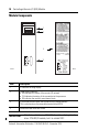
ControlLogix Remote I/O (RIO) Module Module Components 1 RIO CLX OK 2 4 2 3 1 2 Clr 1 44777 Blue 43161 1756-RIO/B Item Description 1 4-character scrolling display 2 Three status indicators: • RIO indicates the status of the remote I/O network • CLX indicates the status of the connection to the processor • OK indicates the module’s own internal state 3 3-pin connector (blue hose) that connects to the remote devices This is also known as the removable terminal block (RTB).
ControlLogix Remote I/O (RIO) Module 11 Power Requirements This module receives power from the 1756-chassis power supply and requires two sources of power from the ControlLogix backplane. • 450 mA at 5.1V DC • 5 mA at 24V DC Add these current/power values (2.5 W) to the requirements of all other modules in the chassis to prevent overloading the power supply. Install the Module You can install or remove the module while chassis power is applied if you observe these precautions.
ControlLogix Remote I/O (RIO) Module Installing and Connecting a Chassis Before installing the module, you must install and connect a ControlLogix chassis and power supply. See ControlLogix Chassis Installation Instructions, publication 1756-IN080. To determine the slot location in the chassis, remember that chassis slots are numbered starting from the left, at 0. Slot 0 is the first slot to the right of the power supply. You can do the following: • Use any size chassis.
ControlLogix Remote I/O (RIO) Module 13 Install the Module in the Chassis To install the module, follow these steps. 1. Align the circuit board with the top and bottom chassis guides. Printed Circuit Board 20861 WARNING: When you insert or the remove the module while backplane power is on, an electrical arc can occur. This could cause an explosion in hazardous location installations. Be sure that power is removed or the area is nonhazardous before proceeding.
ControlLogix Remote I/O (RIO) Module 2. Slide the module into the chassis until the module locking tabs click. Locking Tab 20862 ATTENTION: Do not force the module into the backplane connector. If you cannot seat the module with firm pressure, check the alignment. Forcing the module into the chassis can damage the backplane connector or the module. The module is fully installed when it is flush with the power supply or other installed modules.
ControlLogix Remote I/O (RIO) Module 15 Install the Removable Terminal Block (RTB) Push the removable terminal block (RTB) into the 3-pin connector. 2 2 (Clear) 1 1 (Blue) (Shield) 44776 WARNING: If you connect or disconnect the communication cable with power applied to this module or any device on the network, an electrical arc can occur. This could cause an explosion in hazardous location installations. Be sure that power is removed or the area is nonhazardous before proceeding.
ControlLogix Remote I/O (RIO) Module Wire the Connector for the Remote I/O Network To wire the connector for the remote I/O network, refer to the Cabling and Termination table and follow these steps. Cabling and Termination Connector Pin Description 1 (bottom) Line 1 (blue) N/A Shield 2 Line 2 (clear) 1. Connect Line 1 (blue) of the remote I/O cable to the lower pin on the 1756-RIO module. 2. Connect the shield to the middle pin. 3.
ControlLogix Remote I/O (RIO) Module 17 Select the Proper Resistor Use 82 resistors if the network operates at 230.4 kbps or if the network operates at 57.6 kbps, or 115.2 kbps and none of the devices in this table are present. The maximum number of devices on the network is 32. Use 150 resistors if the network contains any of the devices in this table, or if the network operates at 57.6 kbps or 115.2 kbps and you do not require the network to support more than 16 devices. Device Resistors Cat. No.
ControlLogix Remote I/O (RIO) Module Apply Chassis Power Turn on the chassis power supply. Check Power Supply and Module Status The following indicates the correct power supply status and display indicators for the 1756-RIO module. Chassis Power-supply Status Indicators The chassis power-supply indicator should be green. The module OK status indicator should be solid red immediately after you turn on the chassis power supply and then it turns solid green.
ControlLogix Remote I/O (RIO) Module 19 Module Status Indicators The module has three status indicators to indicate the state of internal operations. The status indicators are labeled RIO, CLX, and OK. 44777 RIO CLX OK RIO Status Indicator – Remote Devices Status The RIO indicator displays the status of the remote I/O network connection. Status varies depending on the mode of the module. Scanner Mode This table shows status in order of priority, highest first.
ControlLogix Remote I/O (RIO) Module Adapter Mode This table shows status in order of priority, highest first. Indicator Status Description RIO Red A frame-receive error has been received in the last second (CRC error, abort, or time-out). Indicator stays red for one second after the error occurs. Flashing red/off One or more racks are not being scanned. Flashing green/off Configuration mismatch on one or more racks. Green All racks are being scanned and there are no configuration mismatches.
ControlLogix Remote I/O (RIO) Module 21 OK Status Indicator – Module Health Indicator Status Description OK Green Indicates that module has passed all power-up diagnostics and is functioning normally. Red Indicates that module start-up diagnostics have failed or a major module fault, such as watchdog time-out or jabber inhibit, has occurred. IMPORTANT If all three status indicators are solid red and the 4-character display shows M#xx, (where xx is the error number), a fatal error has occurred.
ControlLogix Remote I/O (RIO) Module Configure the Module Once installed, your 1756-RIO module must be configured. Refer to the 1756-RIO user manual, publication 1756-UM534, for information on module configuration. Uninstall the Removable Terminal Block (RTB) To remove the RTB, grasp firmly and pull out. 2 1 44776 WARNING: If you connect or disconnect the communication cable with power applied to this module or any device on the network, an electrical arc can occur.
ControlLogix Remote I/O (RIO) Module 23 Uninstall the Module WARNING: When you insert or the remove the module while backplane power is on, an electrical arc can occur. This could cause an explosion in hazardous location installations. Be sure that power is removed or the area is nonhazardous before proceeding. Repeated electrical arcing causes excessive wear to contacts on both the module and its mating connector. Worn contacts may create electrical resistance that can affect module operation.
ControlLogix Remote I/O (RIO) Module Replacing the Module If you are replacing an existing module with an identical one, and you want to resume identical system operation, you must do the following: • Install the new module in the same slot. • Run the configuration program and download the appropriate configuration to the module. • Check that the module has the correct firmware, scanner, or adapter version.
ControlLogix Remote I/O (RIO) Module 25 Specifications Technical Specifications - 1756-RIO Attribute 1756-RIO Module location 1756 ControlLogix chassis Backplane current, max 450 mA @ 5.1V DC 5 mA @ 24 V DC Isolation voltage 50V (continuous), basic insulation type, RIO communication lines to backplane. Type tested at 500V AC for 60 s Power dissipation 2.5 W Screw terminal torque 0.5…0.6 N•m (5…7 lb•in) Wiring category(1) 2 - on communication ports Wire size 0.
ControlLogix Remote I/O (RIO) Module Environmental Specifications - 1756-RIO Attribute 1756-RIO Operating temperature IEC 60068-2-1 (Test Ad, Operating Cold) IEC 60068-2-2 (Test Bd, Operating Dry Heat) IEC 60068-2-14 (Test Nb, Operating Thermal Shock) 0…60 °C (32…140 °F) Nonoperating temperature IEC 60068-2-1 (Test Ab, Unpackaged Nonoperating Cold) IEC 60068-2-2 (Test Bb, Unpackaged Nonoperating Dry Heat) IEC 60068-2-14 (Test Na, Unpackaged Nonoperating Thermal Shock) -40…85 °C (-40…185 °F) Surroun
Environmental Specifications - 1756-RIO Attribute 1756-RIO EFT/B immunity IEC 61000-4-4 ±2 kV at 5 kHz on communication ports Surge transient immunity IEC 61000-4-5 ± 2 kV line-earth (CM) on communication ports Conducted RF immunity IEC 61000-4-6 10V rms with 1 kHz sine-wave 80% AM from 150 kHz…80 MHz Certifications(1) - 1756-RIO Certification(2) 1756-RIO c-UL-us UL Listed Industrial Control Equipment, certified for U.S. and Canada. See UL File E65584.
Additional Resources These documents contain additional information concerning related Rockwell Automation products. Resource Description Industrial Automation Wiring and Grounding Guidelines, publication 1770-4.1 Provides general guidelines for installing a Rockwell Automation industrial system. Product Certification website, http://www.ab.com Provides declarations of conformity, certificates, and other certification details. You can view or download publications at http://www.rockwellautomation.