
User Manual User guide

Publication 1756-UM534B-EN-P - November 2010 133
Scanner Mode I/O Map Appendix A
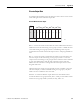
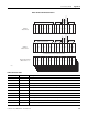
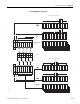
Discrete I/O Data Transfer
Discrete Read Structure - Input
0 1 2 3 4 5 6 7 8 9
Status Codes and
Error Codes
Discrete Input Data
1st
16-bit
Word
I
O
I
I
I
II
II
O
O
O
OOOO
0 1 2 3 4 5 6 7
Group
Group
Group
Group
1/4
Partial Rack
1/4
Partial Rack
1/4
Partial Rack
1/4
Partial Rack
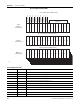
Read
Status Word
0 1 2 3 4 5 6 7 8 9 10 11 12 13 14 15
Oset 2…9
Input Words
8 Words of Discrete Input Data
Status Word
0 1 2 3 4 5 6 7 8 9 10 11 12 13 14 15
Reserved (Pad for 32-bit Alignment)
Reserved
0 1 2 3 4 5 6 7 8 9 10 11 12 13 14 15
Communication Error
1st 1/4 partial rack
Group 0-1/NO ERROR
Communication Error
2nd 1/4 partial rack
Group 2-3/ERROR
Communication Error
3rd 1/4 partial rack
Group 4-5
Communication Error
4th 1/4 partial rack
Group 6-7
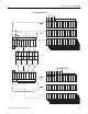
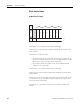
Discrete Write Structure - Ouput
0 1 2 3 4 5 6 7 8 9
2 Control Words
Discrete Output Data
1st
16-bit
Word
Write
Control Word
0 1 2 3 4 5 6 7 8 9 10 11 12 13 14 15
Oset 2…9
Ouput Words
8 Words of Discrete Ouptut Data
Control Word
0 1 2 3 4 5 6 7 8 9 10 11 12 13 14 15
Reserved (Pad for 32-bit Alignment)
Reserved
0 1 2 3 4 5 6 7 8 9 10 11 12 13 14 15
Inhibit Rack
1st 1/4 partial rack
Group 0-1
Inhibit Rack
2nd 1/4 partial rack
Group 2-3
Inhibit Rack
3rd 1/4 partial rack
Group 4-5
Inhibit Rack
4th 1/4 partial rack
Group 6-7
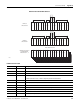
Reset Rack
1st 1/4 partial rack
Group 0-1
Reset Rack
2nd 1/4 partial rack
Group 2-3
Reset Rack
3rd 1/4 partial rack
Group 4-5
Reset Rack
4th 1/4 partial rack
Group 6-7
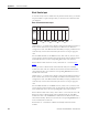
I/O Rack
Scanner Mode
Discrete I/O Data Transfer
44820