
User Manual

Rockwell Automation Publication 1756-UM540A-EN-P - May 2014 89
1756-IRT8I Combined Temperature-sensing Isolated Analog Module Chapter 4
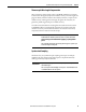
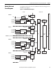
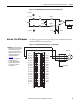
Figure 16 - 1756-IRT8I Module Field-side Circuit with Thermocouple Input
Wire the 1756-IRT8I Module
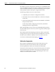
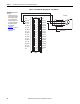
The following graphics show wiring examples for the 1756-IRT8I module used
with RTD and thermocouple input types.
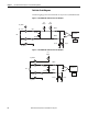
Figure 17 - 1756-IRT8I Module Wiring Diagram - 3-wire RTD Input
0.1 μF
IN_x/RTD D
A/D Converter
IN_x(+)/A
1000 Ω
10 Ω
0.01 μF0.01 μF
1000 Ω
10 Ω
TC
0.01 μF
0.01 μF
IN_x(-)/B
IN_x/RTD C
2.5V Vref
PGA
1
3
5
7
019
1112
4131
6151
8171
0291
2212
4232
6252
8272
0392
2313
33
6353
2
34
8
6
4
CJC 0
IN_0(-)/B
IN_0/RTD C
IN_1(-)/B
IN_1/RTD C
IN_2(-)/B
IN_2/RTD C
IN_3(-)/B
MPORTANT: Remember the following:
• If separate power sources are used, do
not exceed the specific isolation
voltage. For more information on
module specifications, see the 1756
ControlLogix I/O Specifications
Technical Data, publication
1756-TD002
.
• Terminals 1, 2, 35, and 36 are not
used in RTD applications.
• For 2-wire resistor applications
including calibration, make sure
IN_x(-)/B and IN_x/RTD C are
shorted together.
IN_3/RTD C
IN_4(-)/B
IN_4/RTD C
IN_5(-)/B
IN_5/RTD C
IN_6(-)/B
IN_6/RTD C
IN_7(-)/B
IN_7/RTD C
CJC 1
CJC 0
IN_0(+)/A
IN_0/RTD D
IN_1(+)/A
IN_1/RTD D
IN_2(+)/A
IN_2/RTD D
IN_3(+)/A
IN_3/RTD D
IN_4(+)/A
IN_4/RTD D
IN_5(+)/A
IN_5/RTD D
IN_6(+)/A
IN_6/RTD D
IN_7(+)/A
IN_7/RTD D
CJC1
Shield Ground
3-wire RTD