
User Manual

Rockwell Automation Publication 1756-UM540A-EN-P - May 2014 59
1756-IF8I Isolated Analog Input Module Chapter 3
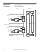
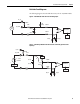
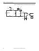
Field-side Circuit Diagrams
The following diagrams show the field-side circuitry for the 1756-IF8I module.
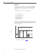
Figure 6 - 1756-IF8I Module Field-side Circuit with Voltage Input
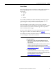
Figure 7 - 1756-IF8I Input Module Field-side Circuit with an Externally-powered Current
Input Loop
RTN-x
1 μA
Pullup
0.1 μF
IN_x/V
A/D Converter
7500 Ω
2.5V Vref
+
IN_x/I/SRC
1000 Ω
55 Ω
0.01 μF0.01 μF
–
1000 Ω
20 Ω
Voltage
Source
0.01 μF
0.01 μF
PGA
RTN-x
0.1 μF
IN_x/V
A/D Converter
7500 Ω
IN_x/I/SRC
1000 Ω
55 Ω
4…20 mA
Transmitte r
0.01 μF0.01 μF
1000 Ω
20 Ω
Transmi tter
Power
0.01 μF
0.01 μF
Current Limit
24.9 Ω
25 Ω
i_sense
2.5V Vref
PGA
+
–
+
–